 Facebook
 Google
 GitHub
 Linkedin
I am new to wiring custom electronics, so I'm reaching out for some help.
I was wondering if I could get some feedback on the wiring of a custom mouse. I am modifying the layout of an open source mouse project.
Link: https://www.lynx-workshop.com/
I am new to wiring electronics, but I think my mods to the original layout are okay but would love some feedback. I messaged the guy behind the open source project, but didn't get super great feedback.
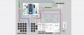
It is the LYNX mouse and I'm changing the sensor from the adns-5050 to the pme-3360. The adns only goes to 1375 dpi and the 3360 goes to 12,000.
I found a GitHub showing how to connect the pmw-3360 to an updated version of the original controller. The controller is the ATMega32u4
GitHub link: https://github.com/SunjunKim/PMW3360_Arduino
Controller link: https://learn.sparkfun.com/tutorials/qwiic-pro-micro-usb-c-atmega32u4-hookup-guide/all
So I kept the encoder wiring the same, I followed the GitHub for the sensor, and wired all the buttons to the leftover green I/O pins.
The attached image with the gray background is the original layout and the one with the white background is my updated layout.
Thanks!
I was wondering if I could get some feedback on the wiring of a custom mouse. I am modifying the layout of an open source mouse project.
Link: https://www.lynx-workshop.com/
I am new to wiring electronics, but I think my mods to the original layout are okay but would love some feedback. I messaged the guy behind the open source project, but didn't get super great feedback.
It is the LYNX mouse and I'm changing the sensor from the adns-5050 to the pme-3360. The adns only goes to 1375 dpi and the 3360 goes to 12,000.
I found a GitHub showing how to connect the pmw-3360 to an updated version of the original controller. The controller is the ATMega32u4
GitHub link: https://github.com/SunjunKim/PMW3360_Arduino
Controller link: https://learn.sparkfun.com/tutorials/qwiic-pro-micro-usb-c-atmega32u4-hookup-guide/all
So I kept the encoder wiring the same, I followed the GitHub for the sensor, and wired all the buttons to the leftover green I/O pins.
The attached image with the gray background is the original layout and the one with the white background is my updated layout.
Thanks!
Attachments
-
 622.7 KB Views: 9
 -
 648.3 KB Views: 9


