custom light project power issue

Thread Starter

Orien Walker

Joined Aug 1, 2016
27
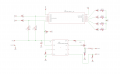
I am designing a custom LED light system. I am using a LM3401 light driver from TI, and a PIC16F1503 MCU from Microchip to provide a PWM signal for dimming and switch and LED controls for a battery indicator. I have the light driver circuit functioning properly on its own, and my MCU circuit functioning properly on its own. When i use the same power source for both circuits, (which is the goal here), my PWM signal coming from my MCU malfunctions and my LED will not fire, it only blinks when i press the switch to activate the PWM signal. If i run the two systems on separate power supplies everything functions properly. I have checked functionality, and the other functions from my MCU are still working when connected to the same supply so my MCU still has power. I believe my issue might be a wiring conflict between the two, but i cannot seem to spot it. Attached is a schematic of the overall system, if anyone has any ideas or solutions they would be greatly appreciated.
 

Attachments

AlbertHall

Joined Jun 4, 2014
12,625
Where does vin2 connect to in this circuit?
Does the PIC have 100nF connected between VDD and VSS very close to the chip?
The LM3401 generates high frequency pulses and you must be careful to make sure none of this gets into the PIC.
 

Thread Starter

Orien Walker

Joined Aug 1, 2016
27
VIN2 and VIN1 are the same power source, just had to name them differently. there is no cap for the PIC. and the LM3401 and PIC are spaced 4 inches apart atm.
 

jpanhalt

Joined Jan 18, 2008
11,087
Why no decoupling cap for the pic?

Hint: If you are using Eagle and you have multiple things with the same name, just name them <name>@x ."x" can be anything. For example, if I have a junction with two connectors (say JP1 and JP2), I will name the parts of the split circuit <name>@JP1 and <name>@JP2.

John
 

eetech00

Joined Jun 8, 2013
4,705
The LM3401 pins don't seem to be connected as shown in the datasheet.
Where is the connection for the pfet source pin power source for example?
 

Thread Starter

Orien Walker

Joined Aug 1, 2016
27
sorry, i made that schematic drawing for this post, and forgot to add in that net between VIN and the PFET source, my bad. there is one there in reality, just an oversight when i put this schematic together.
 

eetech00

Joined Jun 8, 2013
4,705
sorry, i made that schematic drawing for this post, and forgot to add in that net between VIN and the PFET source, my bad. there is one there in reality, just an oversight when i put this schematic together.
please post an accurate representation of your schematic so we can help.
 

Thread Starter

Orien Walker

Joined Aug 1, 2016
27
Any ideas? I've looked at this thing a dozen different ways and cant figure out why the two systems wont work on a singular source. Even having them connected to two different outputs on the same power supply doesn't work. The only way i get them to function properly is if i use a battery pack for one system and a power supply for the other. But they still have to share a common ground...
 
Last edited:

Thread Starter

Orien Walker

Joined Aug 1, 2016
27
The lm3401 and its associated components are on a PCB and the PIC and all of its associated components are still on a BB currently. I don't want to finalize my PCB design for the PIC till I have all the bugs worked out.
 
Top