my project is to use my already alarm setup with ReadSwitchs and Pir Sensor (12V Sensors) mixed into zones
Those zones are in series with a End of Line Resistor.
I need Analog input on the arduino to be able to detect 3 states when alarm is on :
1/ windows are closed and no intrusion => no siren ,
2/ someone open a window or walk in front a PIR sensor => siren
3/ someone try to shut the loop => siren
I want to be able to manage that sensors with a Raspberry or Arduino
So following your advise i will plug a resistor divider before the Arduino or Raspberry to reduce 12V
This divider is composed of 2 Resistors that i need to calculate the value to reduce 12V to 5V
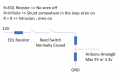
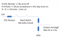
So the schematic should be like this
Please tell me if it make sense ?
Under normal conditions, the switch controls two states: normal and open-loop/fault. In a shorted-loop/tamper condition, the combination of the two-resistor voltage divider and a window-comparator detects the third state.
I am not familiar with active sensors. With passive door reed switches and window tape, someone might attempt to circumvent the NC switches by placing a short across the wires. I still don't see where is the third state. Please excuse my ignorance.
Edit: maybe if the resistor is in the switch, I get it now.
I am not familiar with active sensors. With passive door reed switches and window tape, someone might attempt to circumvent the NC switches by placing a short across the wires. I still don't see where is the third state. Please excuse my ignorance.
Edit: maybe if the resistor is in the switch, I get it now.
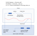
First State , normal state, all reed switchs are normally closed , Resistor of the loop = EOF R Ohm
2nd state, someone open the windows, reed switch is open, Resistor of the loop = infinite Ohm
3rd state, a thief put a shunt somewhere in the loop, Resistor of the loop = 0 Ohm
EOL resistor must be at the end of the loop (hidden in the reed switch sensor)
Burglar must be near the controler (Arduino in my case)
And Only one EOF Resistor per loop
Maybe the missing piece of information is that these type of systems are not wired as a large, single-wire loop that leaves the controller, daisy-chains through the sensors around the area perimeter, and returns to the controller. The wires between sensors/switches are a twisted pair, usually jacketed, so the outbound and return wires always are together. If an evildoer is somewhere in the middle of the loop, and attempts to disable all sensors downstream from his position by shorting the two conductors together with insulation-piercing alligator clips or a razor blade through the insulation, this will be detected as a tamper attempt.
As an added bonus, this type of wiring has *way* less loop area and inductance than a single-wire loop, which reduces its pickup of lightning and other EM events by at least a zillion.
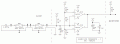
Here is the basic concept, adapted from another forum and thread 5 years ago. Professional panels have more going on, such as transient suppression, current limiting, etc.
The LM393 is a dual version of he quad comparator LM339. The two parts are operationally identical.
I don't know what an Arduino digital input looks like, so R6 might not be needed. The 393/339 has an open-collector output, so the output signal high-state (no fault) voltage is determined by whatever its pull-up impedance is tied to. The Arduino system must have a common GND with this circuit.
If there is a chance that the loop might be extended in the future, put R2 on a stub segment of 1-2 feet, or something long enough not to be visible near the last sensor.
Note - the small stubs are an attempt to show where the connections are between wiring segments.
Since this is a current loop, if you wanted to fool the system you could design an instrument that measures the loop current and then inserts a constant current into the loop.
There is no such thing as perfect security, and any system can be defeated. This technique is a compromise between effectiveness and cost. My guess is that because it is so well known, the main reason it still is used is for loop health monitoring and diagnistics.
There is no such thing as perfect security, and any system can be defeated. This technique is a compromise between effectiveness and cost. My guess is that because it is so well known, the main reason it still is used is for loop health monitoring and diagnistics.
Exactly. How are you going to "insert" a current into a hard-wired, closed-loop system without breaking a wire and being detected? Unless you are talking about attaching a true, high-impedance current source? That would require knowing a lot about the loop characteristics.
I suppose you could separate a short section of the pair, measure the voltage, clamp a DC ammeter around 1 wire to measure the static current, and adjust a battery-powered current sink circuit with the same current and a compliance voltage through a diode so it doesn't conduct any current (possibly lowering the loop voltage to a fault level) until the downstream loop is cut.
Or something like that. But again, that would take detailed knowledge about the loop and input stage parameters.
In fact, if you know the value of the terminating resistor, all you would need is a Shottkey diode and a similar resistor in series, clipped across the wire pair. When the downstream cable is cut, the voltage seen by the controller input stage would jump about 0.3 V, which probably is small enough to get by.
Yes, I am sure that you are clever enough to figure out a way. This is not mission impossible. How long would it take to switch a circuit from 0mA to 6mA? Suppose you had a 6mA current source driving a short (i.e. the loop wire) and then you clip the wire. Would this work?
hi ak
Even if i don't really understand how LM393 works #32 , Is your schematic #32 able to manage the 3 states of the alarm system?
I will buy some LM393 and a couple resitors to test your schematic
thx
hi bend,
As you are using the ADC input of an Arduino, you could write the program to detect and act on the actual voltage levels.
No need for all the OPA's etc.
Which Arduino are you using.?
What is the resistor value of the EOL line.?
My security system uses a PIC for analogue input level sensing
hi bend,
As you are using the ADC input of an Arduino, you could write the program to detect and act on the actual voltage levels.
No need for all the OPA's etc.
Which Arduino are you using.?
What is the resistor value of the EOL line.?
My security system uses a PIC for analogue input level sensing

 Facebook
 Google
 GitHub
 Linkedin