Current transformer from a common-mode choke

Thread Starter

Pyrex

Joined Feb 16, 2022
570
Hi all,
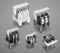
I have a dozen of these common-mode chokes from EMI filters in my box, taken from old fluorescent lamp ballasts and other SMPS power supplies. There's an idea to modify one of them to a current transformer, its windings would be the secondary winding of a current transformer. This choke is made up of two windings, each with about 30-50 turns, and I just need to add a primary winding, which would consist of 2 or 4 turns. I could figure out the exact number of turns with a generator.
There would be about 30 mA of current in the primary winding of the transformer, with a frequency of around 200 kHz.
Is the ferrite on such chokes suitable for working at 200kHz? Has anyone done something similar?
Thanks in aticipation
 

kiroma

Joined Apr 30, 2014
307
Hi.
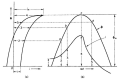
Chokes suitable to work at a given frequency depends on the material of the core. So you have to characterize the core at this frequency you want and also at the power you need. Because the hysteresis loss is dependent on the power you apply, and also the frequency, as 200 kHz is somewhat high. If the core is too slow responding to this stimulus, it leads to distortion, loss in output amplitude, lag, and heating up in the core.
1793880130907.png
Figure: the effects of a sinusoid being too fast for the core.
 
I cannot find a good picture of a CT using a split bobbin from a filter transformer. I have some in the lab.
If you have this type of filter, it should come apart easy. Most transformers are not going to disassemble will.
What I have seen is; one turn of large wire and many turns of small wire. I want a large turn ratio.
1793891944086.png
I test the resonant frequency of the winding that is there now. It needs to be well above your 200khz. That sets the high frequency limit for your CT.
 
This can work well as an experiment, and at 30 mA primary you are in a friendly range — but check three things before trusting the readings:

1. Core material and loss at 200 kHz. Most EMI-filter common-mode chokes use MnZn ferrite, typically high permeability, made to suppress noise in the tens of kHz to a few MHz. That makes 200 kHz plausible, but not guaranteed. If you can find any marking or measure the inductance per turn, compare it with a known MnZn vs. NiZn part. NiZn would give much lower inductance for the same turns. Watch for heating and waveform distortion at 200 kHz — that is the practical sign the core loss is too high.

2. Burden resistor and never an open secondary. A current transformer must always see a low burden. With, say, a 2-turn primary and a 40-turn secondary, 30 mA in the primary gives about 1.5 mA in the secondary, so a 100 ohm burden gives about 0.15 V. Size the burden from I_secondary = I_primary x N_primary / N_secondary, and pick a resistor value that keeps the core out of saturation and the voltage comfortably below your measurement range. Never run it with the secondary open — the voltage can spike high and stress the winding insulation.

3. Winding and insulation practice. Use insulated wire for the primary, keep the primary and secondary well separated, and put a layer of insulation tape between them if you rewind. As ronsimpson said, check the self-resonant frequency of the finished secondary — it should be well above 200 kHz, or the capacitance will distort the reading. A quick bench test helps: drive a known 200 kHz, 30 mA current through the primary, look at the burden voltage on a scope, and check that the waveform is a clean sine and the amplitude scales linearly when you halve the current. If it is linear and cool after a few minutes, the choke is doing fine as a small-signal CT.
 

ronsimpson

Joined Oct 7, 2019
4,866
There would be about 30 mA of current in the primary winding of the transformer
At low current I would use a resistor to measure current. I have never used a CT at less than 1A. If you said 30A or 300A then a CT is a good choice.
Please post what PWM you are using. Or give us more information. There are many ways to see current.
If you are just doing this to have fun and learn, then build the CT and try it.
If you are using a split bobbin like in post #3 then you do not need to insulate the primary, or you can have reduced insulation.
 

kiroma

Joined Apr 30, 2014
307
This can work well as an experiment, and at 30 mA primary you are in a friendly range — but check three things before trusting the readings:

1. Core material and loss at 200 kHz. Most EMI-filter common-mode chokes use MnZn ferrite, typically high permeability, made to suppress noise in the tens of kHz to a few MHz. That makes 200 kHz plausible, but not guaranteed. If you can find any marking or measure the inductance per turn, compare it with a known MnZn vs. NiZn part. NiZn would give much lower inductance for the same turns. Watch for heating and waveform distortion at 200 kHz — that is the practical sign the core loss is too high.

2. Burden resistor and never an open secondary. A current transformer must always see a low burden. With, say, a 2-turn primary and a 40-turn secondary, 30 mA in the primary gives about 1.5 mA in the secondary, so a 100 ohm burden gives about 0.15 V. Size the burden from I_secondary = I_primary x N_primary / N_secondary, and pick a resistor value that keeps the core out of saturation and the voltage comfortably below your measurement range. Never run it with the secondary open — the voltage can spike high and stress the winding insulation.

3. Winding and insulation practice. Use insulated wire for the primary, keep the primary and secondary well separated, and put a layer of insulation tape between them if you rewind. As ronsimpson said, check the self-resonant frequency of the finished secondary — it should be well above 200 kHz, or the capacitance will distort the reading. A quick bench test helps: drive a known 200 kHz, 30 mA current through the primary, look at the burden voltage on a scope, and check that the waveform is a clean sine and the amplitude scales linearly when you halve the current. If it is linear and cool after a few minutes, the choke is doing fine as a small-signal CT.
This answer seems straight from a LLM.
 

Thread Starter

Pyrex

Joined Feb 16, 2022
570
Thanks for the answers,
As I understand, it's necessary to check how the CT will work at 200kHz. I'll do it, it's just that my generator can't produce 30mA current, so I'll wind more turns on the primary coil and a smaller current will be enough.

The CT will be used in the capacitor ESR meter.When measuring ESR, you need to amplify the small voltage, and based on its size, you determine what the ESR is.However, if you want to measure small ESR values, a very small voltage drops across the measurement resistor. So it would make sense to let the current pass through the CT and measure the voltage across the CT's load resistor.Then a smaller gain will be enough, a single-transistor amplifier will do it, instead of a fast OpAmp
 

kiroma

Joined Apr 30, 2014
307
Thanks for the answers,
As I understand, it's necessary to check how the CT will work at 200kHz. I'll do it, it's just that my generator can't produce 30mA current, so I'll wind more turns on the primary coil and a smaller current will be enough.

The CT will be used in the capacitor ESR meter.When measuring ESR, you need to amplify the small voltage, and based on its size, you determine what the ESR is.However, if you want to measure small ESR values, a very small voltage drops across the measurement resistor. So it would make sense to let the current pass through the CT and measure the voltage across the CT's load resistor.Then a smaller gain will be enough, a single-transistor amplifier will do it, instead of a fast OpAmp
That's interesting, I'd want to see the results, whether it was possible and how reproductible it is.
What range of capacitances do you have in mind? What range of ESRs?
 
Hi all,
I have a dozen of these common-mode chokes from EMI filters in my box, taken from old fluorescent lamp ballasts and other SMPS power supplies. There's an idea to modify one of them to a current transformer, its windings would be the secondary winding of a current transformer. This choke is made up of two windings, each with about 30-50 turns, and I just need to add a primary winding, which would consist of 2 or 4 turns. I could figure out the exact number of turns with a generator.
There would be about 30 mA of current in the primary winding of the transformer, with a frequency of around 200 kHz.
Is the ferrite on such chokes suitable for working at 200kHz? Has anyone done something similar?
Thanks in aticipation
At 30 mA, you could probably use the two windings as-is. Or use a shunt resistor and then the transformer becomes a voltage transformer, not a CT.
 

kiroma

Joined Apr 30, 2014
307
It’s meant only for ESR measurement. This is the well-known Lüdens circuit, modified for measuring lower ESR. Measurement range is about 0-3 Ohms
Do you mean it works for any capacitance? It certainly has a limit.
Also, I saw that the Lüdens is analog. Do you want it analog too? If it were digital, you'd have more resolution in the lower range (mili ohm range).
 

kiroma

Joined Apr 30, 2014
307
At 30 mA, you could probably use the two windings as-is. Or use a shunt resistor and then the transformer becomes a voltage transformer, not a CT.
A shunt at 30 mA probably will have a lot of resistance (5 ohms can be a lot) to have some hundreds of mV at the primary to get something at the secondary. Depends on what resistance is acceptable to be the shunt.
 

Thread Starter

Pyrex

Joined Feb 16, 2022
570
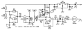
Is this what you are building.
View attachment 373042
Yes, that's the meter.
However, it will be quite modified.The power voltage will be 2.4V, two AA batteries. The oscillator will be a Baxandall oscillator built on two BJTs, sine wave at the output.In place of R6, there would be a CT with a burden resistor. In place of the Opamp U1B, there would be an amplifier built on a BJT.General-purpose opamps don't work well at such a high frequency like 200kHz. This meter is good because, when measuring small ESR values where higher accuracy is needed, the detector works with a higher voltage. Schottky diodes or a small-signal germanium diodes will be used. T1 , R5 and the CT with burden resistor will be placed directly on the measuring probes-tweezers
 

ronsimpson

Joined Oct 7, 2019
4,866
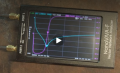
measure ESR on a NANO network analyzer
I know this is off topic. I have network analyzers. This one cost me $100usd. I chose a version that goes down to 10khz and up to 2ghz. The low end interested me more than anything. I often am switching at 100khz to 2mhz. And fighting noise at the switching frequency through 2ghz. I do have one that goes to 10hz but I don't use it because it is hard to make work and cost the price of a car.
I need to know the ESR, ESL and resonant frequency of the caps.
1794068258038.png
 
Top