Current in primary winding of transformer. Help.

Thread Starter

lam58

Joined Jan 3, 2014
69
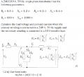
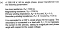
Hi, I have a transformer question here (it's merely a practice question) that I'm a bit stuck on.

The question is in the attached image with all stated values.

My attempt:

Np/Ns=a:

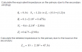
\( I_{s(rated)} = \frac{V_2}{R_L} = \frac{110}{10} = 11A\)

\( E = aV_2+\frac{I_s}{a} (R_sa^2 + jX_sa^2) = a[V_s + I_s(R_s + jX_s)]\)

\( =\frac{23}{11}[110+11(0.1+j0.6)] = 232.3+j13.8V\)

\(If: I_p = I_0 + I'_s \), \(where: I'_s = \frac{I_{s(rated)}}{a}\) and \( I_0 = \frac{E}{R_0} + \frac{E}{jX_0}\)

\( then:I_p = \frac{11}{23/11} +\frac{232.3+j13.8}{1000+j0} + \frac{232.3+j13.8}{0+j1200}\)

\( I_p = 5.5-j0.18 A \) or \( 5.5 \angle -1.9^o\)


The only thing is, my leturer has a similar question in the notes and has attempted the question in a totally different way using lot's of rearranging equations and such. I tried doing it his way but the answer I get does not seem to make sense. Is my above attempt correct?
 

Attachments

Last edited:

MrAl

Joined Jun 17, 2014
11,389
Hi,

I think it would be better if you showed us HIS way of doing it first. We can then gather what he wants you to do and how he wants you to do it.

For example, i doubt you can assume that the output is exactly 110 volts, if that is what you did as part of your calculation. I suppose it is good enough to use to calculate the turns ratio however.

I get different numbers: almost 6 amps and about 5.5 degrees.
For a quick comparison an ideal transformer with 10 ohm load would put 11 amps through it, which would be 5.5 amps in the primary.
But lets see what the guy wanted first.
 
Last edited:

Thread Starter

lam58

Joined Jan 3, 2014
69
Hi,

I think it would be better if you showed us HIS way of doing it first. We can then gather what he wants you to do and how he wants you to do it.

For example, i doubt you can assume that the output is exactly 110 volts, if that is what you did as part of your calculation. I suppose it is good enough to use to calculate the turns ratio however.

I get different numbers: almost 6 amps and about 5.5 degrees.
For a quick comparison an ideal transformer with 10 ohm load would put 11 amps through it, which would be 5.5 amps in the primary.
But lets see what the guy wanted first.
Hi, thanks for the reply. In my answer I did make the V_L assumption just to get Is, however, I thought this would be ok as it was being referred to primary. The example my lecturer gives gets the a similar answer as you despite having slightly different stated values for the components. So I guess my answer is wrong then because you both can't be wrong.

My lecturers example is in the 5 attached images below (note I didn't attach the whole example as I'm only concerned with finding Ip at the moment.)

The part that confuses me is when he states "Now solving for Ip using equations B5 and B6 gives:

\( I_p = \frac{12.42+j9.43}{2.21+j1.93} = 5.42 -j0.46\) Amps

I don't see how he gets from \( I_o =\frac{I_p (48...}{536....}\) to the above equation. I think he puts equation B5 on the left and then rearranges to get I_p, but when I do it I get an answer that is way off.


My attempt:

\( Z_0 = 590.2+j491.8;
Z_p = 0.4+j1;
Z'_p = ( 0.44+j2.6 + 43.7)= (44.14+j2.6)\) (secondary referred to primary)

\( V'_p = V_s - I_p Z_p\)
\( V'_p = I_0 Z_0 \)
\( V'_p =I'_p Z'_p \)

If:

\( V_p - I_p Z_p = I_0 Z_0\)

\( \Rightarrow I_o=\frac{V_p - I_p Z_p}{Z_0}\) equation 1

&

\( I_0Z_0 = I'_pZ'_p\)

Subbing in: \(I'_p=I_pI_0\)

\(\Rightarrow I_oZ_0=(I_p-I_0)Z'_p\)

\(\Rightarrow I_0(Z_0+Z'_p) = I_pZ'_p\)

\(\Rightarrow I_0=\frac{I_pZ'_p}{Z_0+Z'_p}\) equation 2

Using equation 1 and 2:

\( \frac{V_p - I_p Z_p}{Z_0} = \frac{I_pZ'_p}{Z_0+Z'_p}\)

Rearranging and solving for I_p:

\(\Rightarrow I_p=\frac{230(Z_0+Z'_p)}{Z'_pZ_0} + \frac{230}{Z_p}\)

Basically I go from:

\( \frac{230-I_p(0.4+j1)}{590.2+j491.8} = \frac{I_p(44.14+j2.6)}{634.3+j494.4}\)

Rearrange to get I_p:

\( I_p=\frac{230(634.3+j494.4)}{(590.2+j491.8)(44.12+j2.6)} + \frac{230}{0.4+j1}\)

However my finals answer here is just nuts, it's like 216 Amps at -67 degrees.
 

Attachments

Last edited:

jjw

Joined Dec 24, 2013
823
You could use an equivalent circuit of the transformer, where the impedances at the secondary are transferred to primary by multiplying them with a^2. a is Np/Ns.
With Ltspice simulator I got I ~ 5.8A

Edit: I did not notice you had already posted your solution transferring the secondary impedances to primary.
You add the term 230/Zp to primary current, which must be wrong, because Zp is in series with the rest of the circuit.
 
Last edited:

MrAl

Joined Jun 17, 2014
11,389
Reply to post #3 with the entire example posted:

Hi,

That's interesting because when i do it my way (the new example in his notes with 240v in and 110v out) i get about:
5.187-0.6575*j

and when i do it his way (directly from the equations he wrote for B5 and B6) i get:
5.195-0.6581*j

but he manages to get:
5.42-0.46*j

Either way i do it i get an amplitude of about 5.24 and angle around -7 degrees, yet he manages to get around 5.4 at - 5 degrees.

All we can do is guess at this point as to how he rounded his intermediate results during the equation evaluation:
B5=B6

When i copy his notes exactly for these two i get a different result and it closely matches the way i would have done it had i not seen the notes. Maybe he made an error during that evaluation or grossly rounded something.

What you can do is at least try to match the above (about 5.2 -0.66*j) and see what you get.
 

Thread Starter

lam58

Joined Jan 3, 2014
69
You could use an equivalent circuit of the transformer, where the impedances at the secondary are transferred to primary by multiplying them with a^2. a is Np/Ns.
With Ltspice simulator I got I ~ 5.8A

Edit: I did not notice you had already posted your solution transferring the secondary impedances to primary.
You add the term 230/Zp to primary current, which must be wrong, because Zp is in series with the rest of the circuit.
Reply to post #3 with the entire example posted:

Hi,

That's interesting because when i do it my way (the new example in his notes with 240v in and 110v out) i get about:
5.187-0.6575*j

and when i do it his way (directly from the equations he wrote for B5 and B6) i get:
5.195-0.6581*j

but he manages to get:
5.42-0.46*j

Either way i do it i get an amplitude of about 5.24 and angle around -7 degrees, yet he manages to get around 5.4 at - 5 degrees.

All we can do is guess at this point as to how he rounded his intermediate results during the equation evaluation:
B5=B6

When i copy his notes exactly for these two i get a different result and it closely matches the way i would have done it had i not seen the notes. Maybe he made an error during that evaluation or grossly rounded something.

What you can do is at least try to match the above (about 5.2 -0.66*j) and see what you get.

Thanks. I think the way I'm rearranging: \( \frac{V_p - I_p Z_p}{Z_0} = \frac{I_pZ'_p}{Z_0+Z'_p}\) is wrong.


If I take the above and expand out the left term first to make: \( \frac{V_p}{Z_0} - \frac{I_pZ_p}{Z_0} = \frac{I_pZ'_p}{Z_0+Z'_p}\)


Then add: \( \frac{I_pZ_p}{Z_0} \) to both sides to make:

\( \frac{V_p}{Z_0} = \frac{I_pZ'_p}{Z_0+Z'_p} + \frac{I_pZ_p}{Z_0}\)

Then multiply both side by Z_0 to and take out I_p on the right hand side I get:

\( V_p = I_p [\frac{Z'_pZ_0}{Z_0+Z'_p} + Z_p]\)

Thus I_p is:

\( I_p = \frac{V_p}{\frac{Z'_pZ_0}{Z_0+Z'_p} + Z_p}\)

Which basically leaves me with 5.35-j0.613 Amps (5.4 amps at -6.5 degrees)
 
Last edited:

Thread Starter

lam58

Joined Jan 3, 2014
69
I got from the example ( 240V/110V) the same result as MrAl: Ip=5.1867-0.6575j or 5.228A at angle -7.22
Well I'm not sure why my answer isn't the same, I can only guess that I have some rounding errors. However, most marks are gained with the method so in that sense I'm more concerned that my method is right.
 

MrAl

Joined Jun 17, 2014
11,389
Hi again,

Well what you can do is state the logic you used behind your way of doing it.
Also, did you get a result that is very far off or just a little off?

For example, the way i did it first was to simply reflect all impedances to the very input. That way i end up with one single impedance Zin connected to a voltage source of 240 volts AC at 50 Hz. So that way it comes down to calculating Iin=240/Zin which is one complex number.
I got a slightly different result using HIS method because i used HIS original rounding, but with my method i used 16 digit precision for all calculations.

The way i like to do these problems is use 16 or more digits precision right to the very end, and then only at the end, the very last result, do i like to round to some real values. So if i end up with an intermediate calculation of 1.23456789 i'll keep that result intact for all the calculations, then if the final result is 7.23456789 i will round it to maybe 7.235 for short.
This is a good idea because we can loose significant accuracy when differences between numbers that are almost the same are calculated as well as when many multiplications are performed.
 
Last edited:

Thread Starter

lam58

Joined Jan 3, 2014
69
Hi again,

Well what you can do is state the logic you used behind your way of doing it.
Also, did you get a result that is very far off or just a little off?

For example, the way i did it first was to simply reflect all impedances to the very input. That way i end up with one single impedance Zin connected to a voltage source of 240 volts AC at 50 Hz. So that way it comes down to calculating Iin=240/Zin which is one complex number.
I got a slightly different result using HIS method because i used HIS original rounding, but with my method i used 16 digit precision for all calculations.

The way i like to do these problems is use 16 or more digits precision right to the very end, and then only at the end, the very last result, do i like to round to some real values. So if i end up with an intermediate calculation of 1.23456789 i'll keep that result intact for all the calculations, then if the final result is 7.23456789 i will round it to maybe 7.235 for short.
This is a good idea because we can loose significant accuracy when differences between numbers that are almost the same are calculated as well as when many multiplications are performed.

I guess my method is basically a form of thevenins equiv referring all secondary impedances to the primary and then dividing the input voltage by the total circuit impedance, similar to the way you have. My answer isn't too far off tbh, and it's the method that's more important than the answer. Providing the answer is in the general region, rounding errors won't be a problem, at least they never have been in the past.
 

t_n_k

Joined Mar 6, 2009
5,455
Using your equation directly with a math app would give a more precise solution:

Iprim= 5.3445225 - j0.6141940 Amps
|Iprim|= 5.3796984 A
Phase = - 6.5556883 deg

Your solution seems quite OK.
 

jjw

Joined Dec 24, 2013
823
Using your equation directly with a math app would give a more precise solution:

Iprim= 5.3445225 - j0.6141940 Amps
|Iprim|= 5.3796984 A
Phase = - 6.5556883 deg

Your solution seems quite OK.
That is the correct answer with values from the post #1
I and MrAl have been posting answers with values from post #3, where the solution from the lecturer is off by about 4%
 

MrAl

Joined Jun 17, 2014
11,389
I guess my method is basically a form of thevenins equiv referring all secondary impedances to the primary and then dividing the input voltage by the total circuit impedance, similar to the way you have. My answer isn't too far off tbh, and it's the method that's more important than the answer. Providing the answer is in the general region, rounding errors won't be a problem, at least they never have been in the past.
Hello again,

That sounds good to me, you just have to be careful because you will be working with complex numbers, multiplying, dividing, etc., which means keeping track of both real and imag parts for each calculation.

So it seems your approach was the same as mine. I often use this kind of approach where we combine as many impedances as possible when i do it by hand and it works out all the time.

With that in mind, i'll offer the general solution to any transformer circuit like the one shown in the second example with 240v input and 110v output:

First, we have the complex impedance reflected to the primary which is equal to:
Zx=-(Xm*Xp*A*RL-j*Rm*Xp*A*RL-j*Rp*Xm*A*RL-j*Rm*Xm*A*RL-Rm*Rp*A*RL+j*Xm*Xp*Xs*A+Rm*Xp*Xs*A+Rp*Xm*Xs*A+Rm*Xm*Xs*A-j*Rm*Rp*Xs*A+Rs*Xm*Xp*A-j*Rm*Rs*Xp*A-j*Rp*Rs*Xm*A-j*Rm*Rs*Xm*A-Rm*Rp*Rs*A+Rm*Xm*Xp-j*Rm*Rp*Xm)/(j*Xm*A*RL+Rm*A*RL-Xm*Xs*A+j*Rm*Xs*A+j*Rs*Xm*A+Rm*Rs*A+j*Rm*Xm)

Code:
Zx=-(Xm*Xp*A*RL-j*Rm*Xp*A*RL-j*Rp*Xm*A*RL-j*Rm*Xm*A*RL-Rm*Rp*A*RL+j*Xm*Xp*Xs*A+Rm*Xp*Xs*A+Rp*Xm*Xs*A+Rm*Xm*Xs*A-j*Rm*Rp*Xs*A+Rs*Xm*Xp*A-j*Rm*Rs*Xp*A-j*Rp*Rs*Xm*A-j*Rm*Rs*Xm*A-Rm*Rp*Rs*A+Rm*Xm*Xp-j*Rm*Rp*Xm)/(j*Xm*A*RL+Rm*A*RL-Xm*Xs*A+j*Rm*Xs*A+j*Rs*Xm*A+Rm*Rs*A+j*Rm*Xm)
where Rs, Rp, Xs, Xp, Xm are exactly as the example and Rm=R0 of the example as i felt Rm was a better choice of variable. So Rm goes in parallel to Xm as in the example where R0 goes in parallel with Xm. Also RL is the load resistance which was 10 ohms in the example, and A is the turns ratio squared so for the second example it was estimated at 2.18^2 although i used the more 'accurate' (240/110)^2. It's a little more clear to write A than it is to write a^2 that's why i show it that way.

Since Zx above is the entire impedance reflected back to the line, the complex current is:
Ip=Vp/Zx

which for the example would be:
Ip=240/Zx

Now you can do this at least two ways, either compute Zx first and then divide or just do the whole thing at once. Either way we get:
Ip=5.18671099-0.657503915*j

and you can convert that to amplitude and phase angle.

To get this down to a quicker formula, if we call Rn the real part of the numerator and In the imaginary part of the numerator and D the denominator, we have:

Rn=-Vp*((Rm*A*RL-Xm*Xs*A+Rm*Rs*A)*(Xm*Xp*A*RL-Rm*Rp*A*RL+Rm*Xp*Xs*A+Rp*Xm*Xs*
A+Rm*Xm*Xs*A+Rs*Xm*Xp*A-Rm*Rp*Rs*A+Rm*Xm*Xp)-(Xm*A*RL+Rm*Xs*A+Rs*Xm*A+Rm*Xm)*(
Rm*Xp*A*RL+Rp*Xm*A*RL+Rm*Xm*A*RL-Xm*Xp*Xs*A+Rm*Rp*Xs*A+Rm*Rs*Xp*A+Rp*Rs*Xm*A+Rm*
Rs*Xm*A+Rm*Rp*Xm))

and:
In=-Vp*((Xm*A*RL+Rm*Xs*A+Rs*Xm*A+Rm*Xm)*(Xm*Xp*A*RL-Rm*Rp*A*RL+Rm*Xp*Xs*A+
Rp*Xm*Xs*A+Rm*Xm*Xs*A+Rs*Xm*Xp*A-Rm*Rp*Rs*A+Rm*Xm*Xp)+(Rm*A*RL-Xm*Xs*A+Rm*Rs*A)*(
Rm*Xp*A*RL+Rp*Xm*A*RL+Rm*Xm*A*RL-Xm*Xp*Xs*A+Rm*Rp*Xs*A+Rm*Rs*Xp*A+Rp*Rs*Xm*A+Rm*
Rs*Xm*A+Rm*Rp*Xm))

and:
D=(Xm*Xp*A*RL-Rm*Rp*A*RL+Rm*Xp*Xs*A+Rp*Xm*Xs*A+Rm*Xm*Xs*A+Rs*Xm*Xp*A-Rm*Rp*
Rs*A+Rm*Xm*Xp)^(2)+(-Rm*Xp*A*RL-Rp*Xm*A*RL-Rm*Xm*A*RL+Xm*Xp*Xs*A-Rm*Rp*Xs*A-Rm*
Rs*Xp*A-Rp*Rs*Xm*A-Rm*Rs*Xm*A-Rm*Rp*Xm)^(2)


so then we have:
Ip=Rn/D+j*In/D

This might be a little easier to calculate because all the calculations then work with real numbers only until the very end for Ip itself.
 
Last edited:
I guess my method is basically a form of thevenins equiv referring all secondary impedances to the primary and then dividing the input voltage by the total circuit impedance, similar to the way you have. My answer isn't too far off tbh, and it's the method that's more important than the answer. Providing the answer is in the general region, rounding errors won't be a problem, at least they never have been in the past.
Your answer is using the variables from the 230/110 example in post #1. The result given by MrAl in post #5 is using the 240/110 variables from post #3.

PriCurrr.png
 

MrAl

Joined Jun 17, 2014
11,389
Hello there Electrician,

Nice to see your input on this too. You reminded me that the last few digits of the calculation after a calculation like this might not be too accurate, so i rounded my previous result down to 9 significant digits which is still good for comparison yet is probably more accurate than all the digits previously shown.

Here are some slightly more accurate results for comparison using the example with 240v input and 110v output:
5.186710991179218425788385397 - 0.6575039148836521071170997231*j

which calculates out to an amplitude of:
5.228219802581624367331355 Amperes

and angle of:
-7.224679986389701707887324 degrees.

And just to be clear, i used the turns ratio a=240/110 so A=a^2 not the rounded down 2.18 as the instructor did in his example (which is probably good enough though).
 
Last edited:
Top