Current division for inductors

Thread Starter

Ramiel

Joined Feb 19, 2018
74
Hello everyone!!!
First of all I want to say that i understand the way the book came up with the answers, but I was trying to find an alternative way to answer part 1 and .
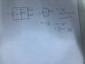
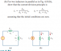
correct me if i am wrong, I know that current division for inductors can be applied just like resistors. so my question is: why cant i find i(t) using the division rule: i1(t)= (3/3+6)i(t). so then i(t) = 3i1(t). and find i2(0) = (6/3+6)i(o). If i use the former equations, the answers will be wrong. Can I know what is wrong with this current division method?
Thanks in advance.

circuit.PNG
 
Last edited by a moderator:

WBahn

Joined Mar 31, 2012
29,978
The reason you can't use the resistor current division formula for inductors is because resistors aren't inductors and they don't obey that rule.

The current division formula is predicated on the fact that if two resistors have the same voltage across them (i.e., are in parallel), then the ratio of the current in the two resistors is proportional to the reciprical of their resistances. This is due to the fact that

I1 = V/R1
I2 = V/R2

I1/I2 = R2/R1

But that simply doesn't hold for inductors, where you have

V1 = L1 (dI1/dt)
V2 = L2 (dI2/dt)

So you get

(dI1/dt) / (dI2/dt) = L2/L1

This, all by itself, means that if the two inductors are different values, then the rate at which the current is changing in each will be different, which means that whatever ratio the currents had at one moment it time, it will be different at the next moment in time.
 

Thread Starter

Ramiel

Joined Feb 19, 2018
74
i used the rule since it was mentioned in one of the questions as proof. I also used the same method for capacitors and it worked. So when can I use the rule mentioned in the attached photo
 

Attachments

WBahn

Joined Mar 31, 2012
29,978
i used the rule since it was mentioned in one of the questions as proof. I also used the same method for capacitors and it worked. So when can I use the rule mentioned in the attached photo
Do... the... math.

For capacitors in parallel:

Q1 = V·C1
Q2 = V·C2

I1 = (dV/dt)·C1
I2 = (dV/dt)·C2

If two capacitors are in parallel, then they have the same voltage and hence the derivative of the voltage across each must also always be the same. Hence

I1/I2 = C1/C2

Stop trying to memorize rules and, instead, learn how to apply the concepts.
 

Thread Starter

Ramiel

Joined Feb 19, 2018
74
Do... the... math.

For capacitors in parallel:

Q1 = V·C1
Q2 = V·C2

I1 = (dV/dt)·C1
I2 = (dV/dt)·C2

If two capacitors are in parallel, then they have the same voltage and hence the derivative of the voltage across each must also always be the same. Hence

I1/I2 = C1/C2

Stop trying to memorize rules and, instead, learn how to apply the concepts.
Okay thanks for the reply
 

Thread Starter

Ramiel

Joined Feb 19, 2018
74
Do... the... math.

For capacitors in parallel:

Q1 = V·C1
Q2 = V·C2

I1 = (dV/dt)·C1
I2 = (dV/dt)·C2

If two capacitors are in parallel, then they have the same voltage and hence the derivative of the voltage across each must also always be the same. Hence

I1/I2 = C1/C2

Stop trying to memorize rules and, instead, learn how to apply the concepts.
I saw the rule and just wanted to apply it, since it facilitates some questions.but I would still appreciate an explanation on why the rule did not work.
 

WBahn

Joined Mar 31, 2012
29,978
I saw the rule and just wanted to apply it, since it facilitates some questions.but I would still appreciate an explanation on why the rule did not work.
I gave you not only an explanation, but a mathematical proof of why it doesn't hold. The defining relationship for an inductor means that two inductors in parallel have proportional CHANGES in current, not proportional current.
 

crutschow

Joined Mar 14, 2008
34,284
If you apply the same time-varying voltage to two inductors in parallel, then their currents will be inversely proportional to their inductance.
 

WBahn

Joined Mar 31, 2012
29,978
If you apply the same time-varying voltage to two inductors in parallel, then their currents will be inversely proportional to their inductance.
Only under a certain assumption that does not apply in this case.

If this claim were true, then since the two paralleled inductors have an L1/L2 inductance ratio of 2:1, i2 should be, at all times, twice i1.

But it isn't.

i1(t) = 0.6 A e ^(t/0.5 s)
i2(t) = -0.4 A + 1.2 A e ^(t/0.5 s)

The initial currents have a i2/i1 ratio of 4/3. At some point i2(t) goes through zero when i1(t) is non-zero, and after than i2(t) and i1(t) aren't even in the same direction, let along proportional to each other. Eventually i1(t) goes to zero and i2(t) goes to -0.4 A.
 

MrAl

Joined Jun 17, 2014
11,389
Hi,

What i would suggest is to look at the ratio of the two inductor currents.
If we had:
i1=i*L1/(L1+L2)
and:
i2=i*L2/(L1+L2)

and we know either i1 or i2, then what helps us is to know the ratio of the two currents either i2/i1 or i1/i2.
I wont say anything else for now about that except that could be a hint :)

Another hint is to look at the initial value of an exponential time function as obtained from the exponential time function itself.

Also, to look into this in a different way, we could do some sinusoidal analysis using the inductor impedances and pure sine sources. That will lead to some relationships similar to what we have seen already.
The nice thing about this is that the two inductor impedances combine pretty easy being in parallel.
 
Last edited:

Thread Starter

Ramiel

Joined Feb 19, 2018
74
Hi,

What i would suggest is to look at the ratio of the two inductor currents.
If we had:
i1=i*L1/(L1+L2)
and:
i2=i*L2/(L1+L2)

and we know either i1 or i2, then what helps us is to know the ratio of the two currents either i2/i1 or i1/i2.
I wont say anything else for now about that except that could be a hint :)

Another hint is to look at the initial value of an exponential time function as obtained from the exponential time function itself.

Also, to look into this in a different way, we could do some sinusoidal analysis using the inductor impedances and pure sine sources. That will lead to some relationships similar to what we have seen already.
The nice thing about this is that the two inductor impedances combine pretty easy being in parallel.
yep thanks got it
 

Thread Starter

Ramiel

Joined Feb 19, 2018
74
okay so here is another question i am stuck at.
first pic is the attempt and the second is the question.
i reached until the integration for i1, but i am not able to find i1(0), help?!!
 

Attachments

Thread Starter

Ramiel

Joined Feb 19, 2018
74
I am the most confused in this topic as i have ever been in my final is in 3 days.
Why did they use current division rule for this question but not the first question although they are almost identical.
I am literally losing my mind
 

Attachments

WBahn

Joined Mar 31, 2012
29,978
I am the most confused in this topic as i have ever been in my final is in 3 days.
Why did they use current division rule for this question but not the first question although they are almost identical.
I am literally losing my mind
Why won't you just do the math? Why do you just want someone else to tell you rules to memorize about when to use memorized rules?

You have an inductor L1 that has a voltage, v(t), across it for all t >= 0 and has an initial current of i1(o) at t=0.

What is the current in this inductor, i1(t), at t > 0?

You have a second inductor, L2, that has the same voltage across it for t >= 0 and that has an initial current in it if i2(0) at t=0.

What is the current in L2 as a function of the current in L1 and the initial currents in both?

What condition has to hold true in order for the current division rule to be applicable?
 

WBahn

Joined Mar 31, 2012
29,978
Hi,

What i would suggest is to look at the ratio of the two inductor currents.
If we had:
i1=i*L1/(L1+L2)
and:
i2=i*L2/(L1+L2)

and we know either i1 or i2, then what helps us is to know the ratio of the two currents either i2/i1 or i1/i2.
I wont say anything else for now about that except that could be a hint :)
You are assuming that those equations are valid. They are NOT valid for the problem the TS is working with.
 

WBahn

Joined Mar 31, 2012
29,978
My eyesight isn't good enough to read that image. Try taking it again without the shadow across it and rotate it so that it can be read directly -- it's good practice to always try to make things easy for the people trying to give you free help.

Remember that when solving a differential equation the initial conditions either have to be given or there has to be additional information that can be used to determine them.

Take it step by step.

You have an inductor L1 that has a voltage, v(t), across it for all t >= 0 and has an initial current of i1(o) at t=0.

What is the current in this inductor, i1(t), at t > 0?

Give your answer in terms of v(t) and i1(0).
 
Top