 Facebook
 Google
 GitHub
 Linkedin
Hey guys,
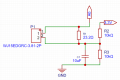
I'm working on a custom PCB to measure the current with a CT-sensor and a Arduino Giga.
I used this article as my reference: https://docs.openenergymonitor.org/electricity-monitoring/ct-sensors/interface-with-arduino.html
This is how my setup look right now:

Connections:
- A6 = analog 6 on the arduino
- P1 = connector to the CT-sensor
Are there any improvements I can implement or does this setup looks good to you guys?
Kind regards,
Rens
I'm working on a custom PCB to measure the current with a CT-sensor and a Arduino Giga.
I used this article as my reference: https://docs.openenergymonitor.org/electricity-monitoring/ct-sensors/interface-with-arduino.html
This is how my setup look right now:
Connections:
- A6 = analog 6 on the arduino
- P1 = connector to the CT-sensor
Are there any improvements I can implement or does this setup looks good to you guys?
Kind regards,
Rens
Attachments
-
 40.9 KB Views: 5
 -
 40.9 KB Views: 5


