CRT TV lissajou/waveform visualizer - Roadstar TV-400N

Thread Starter

Alex Cristian R

Joined Feb 16, 2019
38
Hi!

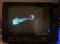
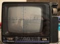
I got a black and white Roadstar TV-400N CRT TV for the purpose of transofrming it in a lissajou visualizer for audio signal. I hooked up the left and right channels of a class D amplifier board to the deflection coil and the lissajou forms started to appear on the screen. They do not look as expected and not precise like on a oscilloscope. I understand that is the due to the non-linear nature of the coils relative to the audio signal.

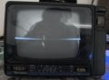
Then i tried to keep one deflection coil connected as factory and feed the other coil with audio signal, rotated the yoke 90 degrees. The waveform appeared on the screen as expected.

The issue is that in the middle of the screen the image is not as the edges when displaying lissajou or waveform of the audio signal. Without any modification the image is fine the screen si equally bright on the entire surface (only tested static, currently i have no means of feeding a proper video signal).

What is causing this brightness imbalance? Can it be improved?


TL;DR: Why is the middle of the screen not bright enough when feeding audio signal directly to the deflection coils?
 

Attachments

WBahn

Joined Mar 31, 2012
33,072
Let's say that you feed the deflection coil with a sinusoid. The beam sweeps back and forth, but where does it spend the majority of its time? At the ends. It is moving slowest there. In the middle, it is moving at it's fasted.
 

Futurist

Joined Apr 8, 2025
925
Hi!

I got a black and white Roadstar TV-400N CRT TV for the purpose of transofrming it in a lissajou visualizer for audio signal. I hooked up the left and right channels of a class D amplifier board to the deflection coil and the lissajou forms started to appear on the screen. They do not look as expected and not precise like on a oscilloscope. I understand that is the due to the non-linear nature of the coils relative to the audio signal.

Then i tried to keep one deflection coil connected as factory and feed the other coil with audio signal, rotated the yoke 90 degrees. The waveform appeared on the screen as expected.

The issue is that in the middle of the screen the image is not as the edges when displaying lissajou or waveform of the audio signal. Without any modification the image is fine the screen si equally bright on the entire surface (only tested static, currently i have no means of feeding a proper video signal).

What is causing this brightness imbalance? Can it be improved?


TL;DR: Why is the middle of the screen not bright enough when feeding audio signal directly to the deflection coils?
Apply DC, get the dot centered, adjust the DC voltage gradually, on X, then Y, then both, then decide what the min/max voltages are for X and Y to get full deflections. Then determine if the deflection is proportional to voltage.

If those tests give different results to a scope then those differences will likely be the cause of the weirdness you see.

Also the deflection system on a CRT TV operates at (low, in the case of the vertical) fixed frequencies, there might be filtering or limiting in place that inhibits arbitrary deflection frequencies, vertical is around 60Hz and horizontal is around 16KHz.

CRT scopes never relied on magnetic deflection because the inductance and so on, heavily impacts beam deflection frequencies and response times.
 
Last edited:

MisterBill2

Joined Jan 23, 2018
27,980
I experimenated with a "TV-Scope" back in the mid 1960's. I had an OLD round screen TV with a 10BP4 CRT, that did not use a flyback transformer, driven by the horizontal sweep tube, to produce the hivh voltage. instead it used a 6V6 driving a air-core step up transformer, and still, a 1B3 rectifier, to produce the second anode voltage.
So it was simple to use a neon bulb relaxation oscillator to produce a sawtooth wave to drive the horizontal amplifier tube. THAT scheme worked well enough to give the "really cool music wave" show. The vertical sweep output when driven by the music signal was adequate. The problem was that the setup was way too big for the rest of the system.Certainly a flat-screen monitor would be great, but without using a full computer to produce the wave-form image the electronics will be quite complex. The system will need to address pixels. WAY too complex.
 

MrChips

Joined Oct 2, 2009
35,018
I did a TV Stereo Scope display many years ago. I don't remember the details.
One of the problem is that you need sufficient differences in the stereo channels in order to get exciting images.
Theoretically, if you put a sinewave into both X and Y channels you should get a straight line inclined at 45°, less bright in the middle. If you can shift the phase of one channel by 90° then you should see a circle.

For music content, you only need to add the phase shift at the lower frequencies, say below 400Hz.
 

Externet

Joined Nov 29, 2005
2,662
I made one from a surveillance monitor; and does not misbehave at the center of the CRT. Did it by feeding L, R audio channels to the H, V deflection coils.
Sorry, the video did not attach; just the image :

1781551810721.png

The one projecting lissajous to the wall from canibalized projection TV guts is taking too long to complete :-(

1781552282610.png

Perhaps some day...
 
Last edited:

MisterBill2

Joined Jan 23, 2018
27,980
Using a TV-type CRT for an audio display has two separate tasks: First, supplying the CRT with the required voltages, and focus arrangement, and second, matching the deflection signals to the deflection yoke. At least, matching to the yoke was always my challenge, since I was just using audio amplifiers to drive them.
 

MisterBill2

Joined Jan 23, 2018
27,980
Here is a bit of caution: The display of musical waveforms has a tendency "to get old" after a few hours! That was my experience back in 1964. Yes, it is "Really Cool", and often impressive! But how long does that last??
THAT is the challenge.
 

Thread Starter

Alex Cristian R

Joined Feb 16, 2019
38
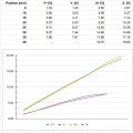
@Futurist I don't have a proper lab supply but i managed to take some measurements. I did not center the beam to the screen, i just measured from it's position when no votage it's supplied to any of the deflection coils. As expected the horizontal axis require more voltage. I don't have a scope CRT, did you mean to power the scope CRT directly like the TV CRT?

@MisterBill2 Indeed, watching lissajous gets old over time.

@MrChips I used a class D amplifier (XH-A232 TPA3110), but strangely, when i feed only one channel with audio the other channel is still active. It acts like it's mono and adjusting each channel level individually does not affect the deflection only on that axis.

Adding a 10k resistor in parallel with the deflection coils seem to fix this problem, the lissajou figures are predictable, measured 1V peak to peak across the coils of both channels before the amplifier started to distort. The figures went to only 1/2 of the screen size and with sine wave i managed to get a clean oval shape.

I managed to get a clean circle with a series resistor of 4ohms with the coils, but the figures were really small, 1/5 of the screen size. Probably a more powerfull amplifier will get me to bigger figures?

@Externet Yours seems to work fine. What kind of amplifier did you use?


Other observations:
- with lights on, the figures are barely visible
- somehow the sound creeps into the TV amplifier and i can hear it (distorted) in it's own speaker. The separate class D amplifier i use to drive the deflection coils is powered with 20V from the TV circuit board.
 

Attachments

MisterBill2

Joined Jan 23, 2018
27,980
I am guessing that it is a transistor television, but maybe not. The television I modified was a mix of octal and miniature tubes. Easy to work on, plenty of room.
 

Externet

Joined Nov 29, 2005
2,662
Yours seems to work fine. What kind of amplifier did you use?
Yes, it does work very well; much better seen at night. I use a dedicated Clarion ET-301C 'ĺine' level input automotive audio power amplifier salvaged out of a defunct Mazda RX7 residing in my canibalizeds/wreck yard bin, fed by a laptop supply. Each channel directly connected to each yoke coil.

My LCD oscilloscope on XY mode does not show an image as neat as a CRT oscilloscope.
 
Last edited:

nsaspook

Joined Aug 27, 2009
16,430
Yes, it does work very well; much better seen at night. I use a dedicated Clarion ET-301C 'ĺine' level input automotive audio power amplifier salvaged out of a defunct Mazda RX7 residing in my canibalizeds/wreck yard bin, fed by a laptop supply. Each channel directly connected to each yoke coil.

My LCD oscilloscope on XY mode does not show an image as neat as a CRT.
A CRT scope is much better.

LCD scope

CRT scope
 

MisterBill2

Joined Jan 23, 2018
27,980
I only used mine for music waveform display. That was cool at the time, I was still in my first year of High school, new to the area and new to the state. So I needed something to be interested in. A sinewave sweep made the center of the display the most detailed. Not useful but cool to watch. Plus, with a constant sine wave sweep, no burning dot in the centerwhen the music stops. THAT setup was big. If I get a portable TV with maybe a 15 or 17 inch screen, and move the high voltage supply to that enclosure, that might be good enough. But now, used CRT portable TV sets are fairly rare. At least around here. And those available are not cheap or free any more.
Making a flat screen display show any sort of waveform will take quite a bit of design effort, simply because those flat screen displays are all digital.
 
Last edited:
Top