Crowbar Circuit best placement of fuse

Thread Starter

KNair

Joined Sep 26, 2024
4
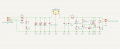
Hello, I am making a replacement linear power supply for a radio receiver. I have drafted two circuits that implement the rectification and regulation of a 6V output.

Linear_PSU_Crowbar_with_Simple_Fuse.png
Schematic 1 - Fuse in conventional position for a Crowbar circuit.

Linear_PSU_Crowbar_with_Diode.png
Schematic 2 - Fuse before regulator with diode to protect the regulator.

My question is which fuse placement is best in practice? I am concerned that the capacitors on the input side of the regulator might delay the operation of the fuse. Would that be the case, or would the fuse blow in time to save the regulator? Or should I stick to the circuit in schematic 1? Your input and advice is most welcome!
 

Ian0

Joined Aug 7, 2020
13,097
Schematic 2 will blow the fuse if the regulator fails. It may also blow the fuse on startup as the capacitors charge.

By the way, your TL431 won't work. The thyristor will be gated ON all the time because the cathode voltage of a TL431 never goes below 2.5V.
Even if you did put a zener in the thyristor gate to lose than 2.5V, it would work the wrong way round, and gate the thyristor ON if the voltage was LESS than 6V.
 

Thread Starter

KNair

Joined Sep 26, 2024
4
Schematic 2 will blow the fuse if the regulator fails. It may also blow the fuse on startup as the capacitors charge.

By the way, your TL431 won't work. The thyristor will be gated ON all the time because the cathode voltage of a TL431 never goes below 2.5V.
Even if you did put a zener in the thyristor gate to lose than 2.5V, it would work the wrong way round, and gate the thyristor ON if the voltage was LESS than 6V.
Thank you for your advice. The amended schematic is below.

Linear_PSU_Crowbar_with_Simple_Fuse+Triac_02.png
Schematic 3.

I have replaced the BT137 with a BT136 triac. In normal operation 6V from the LM7806 should give 2.269v at the trigger for U2, 6.5V will raise V to the TL431's 2.5V trigger threshold.

On the question of protecting the rectifier, how could that best be achieved with the relatively large capacitors on the input? Would some sort of soft-start be required on the rectifier side of the fuse if it was located as per Schematic 2? I don't want to reduce the circuit's reliability on startup.
 

Attachments

Ian0

Joined Aug 7, 2020
13,097
I have replaced the BT137 with a BT136 triac. In normal operation 6V from the LM7806 should give 2.269v at the trigger for U2, 6.5V will raise V to the TL431's 2.5V trigger threshold.
That‘s not going to help. Both triacs and thyristors will trigger with 0.6V on the gate, and the cathode voltage of the TL431 is always more tha 2.5V. Therefore the triac or thyristor will always be on.
On the question of protecting the rectifier, how could that best be achieved with the relatively large capacitors on the input? Would some sort of soft-start be required on the rectifier side of the fuse if it was located as per Schematic 2? I don't want to reduce the circuit's reliability on startup.
That depends on what is supplying the power. If it is a small transformer the winding resistance will limit the current. If it is a large transformer, you might try an NTC inrush suppressor.
 

crutschow

Joined Mar 14, 2008
38,316
That‘s not going to help. Both triacs and thyristors will trigger with 0.6V on the gate, and the cathode voltage of the TL431 is always more tha 2.5V. Therefore the triac or thyristor will always be on.
The crowbar circuit below using a TRIAC is from the TL431 data sheet:
So the TS's circuit should work if the TRIAC is turned upside-down.

1727365291725.png
 

Ian0

Joined Aug 7, 2020
13,097
Yes.
I typically allow for 1mA.

The TS's circuit shows a value of 220E, which is fine if that is 220Ω.
Where did this "E" come from? I saw it on a packet of resistors today (instead of a Ω sign). I could understand it if we were still in the old pre-Unicode days.
 

Thread Starter

KNair

Joined Sep 26, 2024
4
That‘s not going to help. Both triacs and thyristors will trigger with 0.6V on the gate, and the cathode voltage of the TL431 is always more tha 2.5V. Therefore the triac or thyristor will always be on.

That depends on what is supplying the power. If it is a small transformer the winding resistance will limit the current. If it is a large transformer, you might try an NTC inrush suppressor.
Thanks for all the feedback! Now I understand the correct orientation of the triac and how the gate should be connected (after your and crutschow's comments, re-reading the datasheets, and watching some instructional videos I've learned quite a bit.) I had mistaken "bidirectional" as synonymous with, "can be put in a circuit either way round" which is not true.

VIC_9V_center_tap_220V_transformer.jpg
9V Center Tapped 220V Transformer

The photo shows a 9V transformer connected to a prototype circuit I constructed which has a little too much ripple for the downstream receiver. Hence the need for the new circuit design. There are Class X and Class Y capacitors on the mains input socket together with a ferrite and a fuse. The transformer is 220V to 9V center tapped. Although the circuit works now (the current draw is less than 300mA) if anything the transformer might be too small. Nonetheless an NTC inrush suppressor can go on the input before the capacitors. I'm researching their specification now and I will post an updated schematic later.
 

Thread Starter

KNair

Joined Sep 26, 2024
4
Linear_PSU_Crowbar_with_Fuse+Diode+Triac+NTC_03.png
Schematic 4 with NTC Surge Suppressor and diode bypass.

I need to re-calculate the voltage drop over the circuit and check the transformer is adequate. It's easy to replace (I have a good source of transformers) and I can re-use the 9V transformer in a 5V version of this circuit. I will create the PCB files over the weekend, and if there are no other changes order some boards next week. Thanks to everyone's help!
 
Top