Facebook
 Google
 GitHub
 Linkedin
Hi Forum,
My names Chris and I'm a senior in high-school and at the moment I am working on my senior project. For my project I plan to create a pair of electrostatic speakers.
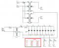
These speakers require a high voltage dc bias which I am trying to satisfy with a crockoft-walton generator. I created a PCB to do this, but it is acting up.
To create my circuit I unashamedly based it on a fully functional one by Jazzman and slightly modified it. The only component changes I have made are doubling the the output resistor(R3) from 11M to 20M and reducing the capacitance of the caps from 5 uf to 4.7uf and choosing polyprop caps.
For safety and guidance, I am working with my physics teacher and my mentors at Microsoft, but they are stumped and don't really have too much time to look into it so I was wondering if you guys could help me out.
The Problem
At different tapping points my circuit should be putting out -2,000-4,000V DC instead my circuit is putting out around -250V DC.
The circuit seems to work for the first node. The voltage across C6 is -590V DC up. However after this my circuit acts like a reverse voltage multiplier.
My Testing:
-Chris

My names Chris and I'm a senior in high-school and at the moment I am working on my senior project. For my project I plan to create a pair of electrostatic speakers.
These speakers require a high voltage dc bias which I am trying to satisfy with a crockoft-walton generator. I created a PCB to do this, but it is acting up.
To create my circuit I unashamedly based it on a fully functional one by Jazzman and slightly modified it. The only component changes I have made are doubling the the output resistor(R3) from 11M to 20M and reducing the capacitance of the caps from 5 uf to 4.7uf and choosing polyprop caps.
For safety and guidance, I am working with my physics teacher and my mentors at Microsoft, but they are stumped and don't really have too much time to look into it so I was wondering if you guys could help me out.
The Problem
At different tapping points my circuit should be putting out -2,000-4,000V DC instead my circuit is putting out around -250V DC.
The circuit seems to work for the first node. The voltage across C6 is -590V DC up. However after this my circuit acts like a reverse voltage multiplier.
My Testing:
- The diodes are facing the right way
- The transformer is putting out the proper voltage
- The routing is correct
-Chris
")