I have a 12 V SPDT relayCan you buy a relay for Rs. 50?
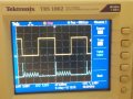
I have a 5 v dc spdt relay and a 12 v dc spdt relay can use either of them.When I threw the unit together to make the waveforms shown in post #14, I used a 5v relay because that happens to be what I grabbed first. Is your relay a 12vDC or 12vAC relay. Just be sure to use 12VDC for your experiment. If you wire it up as shown in the post #8 diagram, it won't really matter but the waveform expected may be a little different because of the shading pole built into an AC relay.
I have a 12V DC battery , how to check if the voltage source matches the coil requirement? Its better that I clarify all of my silly doubt's in order to learn electronics well. Thanks.What kind of power supply do you have? Voltage source should match coil requirement if possible.
I told the retailer to give me a 12 V DC SPDT relayYou said you had a 12V SPDT relay. How did you determine that?
Made a circuit of an astable timer by connecting it with a relay circuit. Please let me know if it is correct. I cannot see an output waveform on the CRO after simulating this ckt. I am new on simulating designs so there might be some silly errors. Using Proteus.Then the 12v battery and the circuit with the NC (Normally Closed) contacts in series with the coil and battery should do it. That makes a buzzer.
I wonder how did you show me the waveforms with the diode and without it earlier ? BTW i will be doing it on the scope. does this circuit look correct for my purpose ?Simulation probably won't work for you. Simulations probably don't activate relays and act upon the results. Build the real thing with your 12V battery and 12v relay and look at the coil with a scope.


HiBill's buzzer is simple, but the operation is somewhat aperiodic. The relay coil current will also not reach steady-state before the contacts open and a new cycle begins.
The 555 oscillator makes a more repeatable 'scope trace, and the dwell is sufficient for the relay coil current to settle down before the coil is switched off. Here is the diode current and the voltage at the collector of the transistor with the diode in place:
View attachment 84938
Now, ask yourself what the voltage at V(col) would be if the diode is not there. Can you find a transistor that will not suffer breakdown with no diode to protect it? Note that Spice transistor models do not account for breakdown...
View attachment 84939
Channel 1 is timer's On - Off trace and channel 2 is Transistor's trace.. When the timer turns off transistor turns off and again swings to On state and becomes unstable.What are the traces?
Not able to understand this behaviour of the transistor. Ideally it should turn off till the timer is off.Channel 1 is timer's On - Off trace and channel 2 is Transistor's trace.. When the timer turns off transistor turns off and again swings to On state and becomes unstable.
| Thread starter | Similar threads | Forum | Replies | Date |
|---|---|---|---|---|
| E | EXPERTS - Check my PCB design, made with AI | PCB Layout , EDA & Simulations | 7 | |
| K | Ps4 pro zapped components.. | Technical Repair | 1 | |
|
|
Assistance from Android experts, please ? | Off-Topic | 3 | |
| P | Ki-CAD experts please help! | Homework Help | 0 | |
| N | BJT experts answer please... | Homework Help | 3 |