CRO experts please help

Thread Starter

Pratik_S

Joined Apr 14, 2015
49
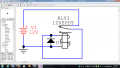
How do i make a circuit using less than 20 components to see the existence and non existence of a flyback diode in which the circuit drives an inductor load . I have a budget constraint of Rs. 50 so please avoid suggesting costly components. I have to see the results on a CRO. A simplified answer would be appreciated . I can also modify the attached circuit which i have already made. But in this circuit i could not see the output on the CRO as the time in which the output occured was very small. Now if i want to see the output what will i have to do to ?Thanks in advance.

20150413_105353s.jpg
 

Papabravo

Joined Feb 24, 2006
21,228
I don't think I can meet the cost constraint. I can't even pay for the shipping with that meager amount. One of the problems with driving an inductive load without the diode is that the device gets destroyed. This is very hard on the budget. Can't you just take it on faith that the diode is necessary?

It is also considered rude to post big picture files.
 
Last edited:

MikeML

Joined Oct 2, 2009
5,444
Does does the cost constraint include the cost of the CRO?

Is the CRO a digital one capable of recording and displaying a single event?

If no, or do you need to repeat the experiment at > 50 times per second so that eye can see it?
 

Thread Starter

Pratik_S

Joined Apr 14, 2015
49
Does does the cost constraint include the cost of the CRO?

Is the CRO a digital one capable of recording and displaying a single event?

If no, or do you need to repeat the experiment at > 50 times per second so that eye can see it?
The cost doesn't include the cost of the CRO , its not a digital one so I can't store the value. I will have to repeat the event . What components will I need to do that?
 

Papabravo

Joined Feb 24, 2006
21,228
The current value of the Rs., according to Google, is $.0098, or about a penny. So Rs. 50 is about half a dollar. Tough budget constraint if you don't have a junk box laying around.
 

Thread Starter

Pratik_S

Joined Apr 14, 2015
49
The transistor driver is labeled as TRANSISTOR SWITCH in the drawing you show in Post #1. Are you asking how that works?
No I thought you are talking about something else. So you mean that if I remove the transistor from the circuit it will show a repeated waveform? Can you explain that?
 

BillB3857

Joined Feb 28, 2009
2,571
If you look at the circuit I posted, the relay Normally Closed contact is in series with the power supply. When you apply power, the relay will pick up, opening the circuit, at which time the relay will drop out. When it drops out, the contacts will close and the relay will pick up again. The cycle repeats as long as power is connected. Simple DC operated door bells and buzzers work that way.
WithDiode.png WithoutDiode.png

Waveform on left is with a diode across the coil, and waveform on right is with diode removed. This is made using a 5v relay with a 5vDC supply.
 

BillB3857

Joined Feb 28, 2009
2,571
The relay setup uses three components... Power source, relay, diode. The 555 astable uses many more and requires more assembly. Your choice. Also, using solid state components, as shown in post #1, you run the risk of damage to the transistor when not using the diode. That is the purpose of having it there to begin with.
 

Thread Starter

Pratik_S

Joined Apr 14, 2015
49
The relay setup uses three components... Power source, relay, diode. The 555 astable uses many more and requires more assembly. Your choice. Also, using solid state components, as shown in post #1, you run the risk of damage to the transistor when not using the diode. That is the purpose of having it there to begin with.
Can you show what circuit is needed if i use a timer 555 astable. I want to compare both possibilities by implementing them.
 

BillB3857

Joined Feb 28, 2009
2,571
Look up 555 astable diagram and connect the output to the circuit shown in post #1. A search on this site should show many 555 circuits. My spoon has a short handle.
 
Top