Creating square wave, triangle wave and sine wave using LM348 op amp on a breadboard

Thread Starter

EvilGenius2222

Joined Sep 16, 2018
9
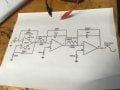
I was given the picture below to build the op amp on a breadboard

I tried using a LM348 op amp with the given resistors and capacitors but it didn't work. I havent used a breadboard in a while and followed the examples online but im doing something wrong. Any help would be greatly appreciated.
 

dl324

Joined Mar 30, 2015
16,921
The picture didn't get posted.

LM348 has the characteristics of a 741, so it has a number of limitations.

A close up, well focused photo of your breadboard layout would also be helpful since you question your ability. Before you post the picture, look at it from our perspective. Are details that we need to see captured and clearly visible?
 

Thread Starter

EvilGenius2222

Joined Sep 16, 2018
9
The picture didn't get posted.

LM348 has the characteristics of a 741, so it has a number of limitations.

A close up, well focused photo of your breadboard layout would also be helpful since you question your ability. Before you post the picture, look at it from our perspective. Are details that we need to see captured and clearly visible?
I will get a photo of it as soon as possible.
 

crutschow

Joined Mar 14, 2008
34,450
That circuit needs a plus and minus voltage to power the op amp (two supplies).
Is that what you have.

If you only have a single supply then you need to add a virtual ground circuit at 1/2 the supply voltage to connect the the three circuit ground points on the bottom to.
That could be as simple as two 1kΩ resistors in series connected from the supply to ground with a 10μF capacitor to ground at the resistors' junction (which is the virtual ground point).
 

KeithWalker

Joined Jul 10, 2017
3,093
Hello,

How difficult is it to post a straight image:

View attachment 161926

Bertus
There are a number of points on the circuit shown as being connected to ground. This is the ground reference point for the outputs. Do NOT connect them to the negative supply.
If you are displaying the output on an oscilloscope, make sure there is no connection between the scope ground and the power supply ground.
 

bertus

Joined Apr 5, 2008
22,277
Hello,

As @MrChips said, where is the power connected?
As the schematic shows a double powersupply, you could use 2 9 volts batteries to power the circuit.

Bertus
 

dl324

Joined Mar 30, 2015
16,921
As already noted, you don't have any power connections.

Relevant portion of the breadboard:
upload_2018-10-19_11-23-37.png

I see 2 100k, a 11k resistors. What is the value of the cap? What supply voltages do you plan to use?

EDIT: On second thought, the odd resistor could be 22k and the cap is too small to be 1uF...
 
Last edited:

John_2016

Joined Nov 23, 2016
55
Hi EG2

remove all passive components and start all over.

some of the reasons to recommend such drastic action are:

1. the 1k resistor is probably making contact with the ceramic capacitor.
2. the 10k and 1k resistors left pins, go, no where?
3. as pointed above, start with the power rails, bring power to the IC, check it works, and then start adding passive components using as many additional tracks as needed
4. keep the components as flat as possible, you have piled up 3 resistors while there's plenty of space and available tracks to avoid that.

Please let us know once this oscillator starts working by posting a scope screen

Regards

John BG
 

ArakelTheDragon

Joined Nov 18, 2016
1,362
Lets start with this: what is your level of electronics knowledge? Do you know Ohm' law? This is not to offend you, but so we may estimate if we should help you.
 
Top