 Facebook
 Google
 GitHub
 Linkedin
Hello Friends,
Since this is my first post; I should introduce myself. My name is Jeffrey and I live in Houston, Texas. My college degrees are in marketing, M Business Administration and M International Business. I wish I had taken engineering, because I am fascinated, curious, excited and frustrated, but determined to learn, understand and create. I have spent countless hours reading All About Circuits and the forums, Wikipedia Electronics and a vast number of hyper-links across the industry to datasheets, tutorials, etc. I am willing to spend my time studying/learning, seeking and researching so that I can make something with my own hands. I don't want someone else to do the work for me, but I realize that at some point it is time to ask for help. I have done the necessary footwork (mouse clicking) so that I can ask the right questions and understand the answers.
Borrowing the Sir Isaac Newton quote: "If I have seen further, it is by standing on the shoulders of giants". I need some help from the giants here.
Goal: Create IC that will switch on motor for 20 seconds (Distance*time) once every 24, 36, 48 or 72 hours (Cycle Time).
I discovered the 555 chip timer at my local electronics shop as part of a kit from Ramsey electronics ($10) that comes with a PCB and the basic resistors, capacitors and pot to make a timer with an output. I got a relay to start the 12v motor with the output of the kit. The next requirement is to trigger the timer (Dt) on a desired cycle time (24, 36, 48 or 72 hours).
The 555 kit is inexpensive, so I plan to purchase another for CT. However, I am in development and open to suggestions. That said, how do I trigger timer Dt with timer CT? So that timer CT provides the pulse required to trigger Dt and then restart CT timing period for the next cycle?
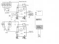
I have created and attached a labeled circuit diagram that is modified from the original diagram that came with the kit. The Philips Electronics Data sheet mentions a method called AC Coupling and shows a diagram that involves two inputs: one 10k resistor and a .001uF with another 10k resistor. I have drawn a copy of their diagram next to the Dt trigger.
Since this is my first post; I should introduce myself. My name is Jeffrey and I live in Houston, Texas. My college degrees are in marketing, M Business Administration and M International Business. I wish I had taken engineering, because I am fascinated, curious, excited and frustrated, but determined to learn, understand and create. I have spent countless hours reading All About Circuits and the forums, Wikipedia Electronics and a vast number of hyper-links across the industry to datasheets, tutorials, etc. I am willing to spend my time studying/learning, seeking and researching so that I can make something with my own hands. I don't want someone else to do the work for me, but I realize that at some point it is time to ask for help. I have done the necessary footwork (mouse clicking) so that I can ask the right questions and understand the answers.
Borrowing the Sir Isaac Newton quote: "If I have seen further, it is by standing on the shoulders of giants". I need some help from the giants here.
Goal: Create IC that will switch on motor for 20 seconds (Distance*time) once every 24, 36, 48 or 72 hours (Cycle Time).
I discovered the 555 chip timer at my local electronics shop as part of a kit from Ramsey electronics ($10) that comes with a PCB and the basic resistors, capacitors and pot to make a timer with an output. I got a relay to start the 12v motor with the output of the kit. The next requirement is to trigger the timer (Dt) on a desired cycle time (24, 36, 48 or 72 hours).
The 555 kit is inexpensive, so I plan to purchase another for CT. However, I am in development and open to suggestions. That said, how do I trigger timer Dt with timer CT? So that timer CT provides the pulse required to trigger Dt and then restart CT timing period for the next cycle?
I have created and attached a labeled circuit diagram that is modified from the original diagram that came with the kit. The Philips Electronics Data sheet mentions a method called AC Coupling and shows a diagram that involves two inputs: one 10k resistor and a .001uF with another 10k resistor. I have drawn a copy of their diagram next to the Dt trigger.
Attachments
-
 85.5 KB Views: 176


