 Facebook
 Google
 GitHub
 Linkedin
Last year I built a bicycle powered generator as a demo at a kids science fair using a permanent magnet motor as the generator. The generator powered an inverter so that the kids could get an idea of how much more power is needed to power an incandescent light bulb than an LED or CFL bulb.
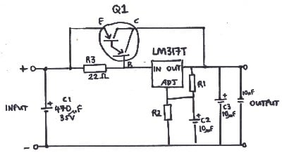
To keep the voltage from rising above 13.8 volts I used an LM317 regulator circuit. I found the circuit design on a renewable energy web site in the U.K.
This is the circuit that I used. It worked well. The darlington transistor carried most of the current but needed a substantial heat sink and fan when the power consumption increased.
http://www.reuk.co.uk/LM317-High-Current-Voltage-Regulator.htm
I found another circuit on the web site that they claim will handle much more current and uses 2N3055 transistors. These would be able to handle more current and dissipate the heat better.
http://www.reuk.co.uk/LM317-Adjustable-Power-Supply.htm
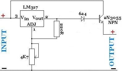
They suggest that more transistors can be added in parallel to increase the current capacity but the circuit is different between the LM317 out and the base of the transistors. I'm not sure why they are different.

I did a circuit simulation using "Do Circuits" and neither one of these will work. The one at the top that I used last year works fine in the simulation but these do not. I haven't bread boarded the circuit yet, but maybe I should try.
Does anyone think that these should work?
If not, would you have any suggestions on something different?
Thanks
To keep the voltage from rising above 13.8 volts I used an LM317 regulator circuit. I found the circuit design on a renewable energy web site in the U.K.
This is the circuit that I used. It worked well. The darlington transistor carried most of the current but needed a substantial heat sink and fan when the power consumption increased.
http://www.reuk.co.uk/LM317-High-Current-Voltage-Regulator.htm
I found another circuit on the web site that they claim will handle much more current and uses 2N3055 transistors. These would be able to handle more current and dissipate the heat better.
http://www.reuk.co.uk/LM317-Adjustable-Power-Supply.htm
They suggest that more transistors can be added in parallel to increase the current capacity but the circuit is different between the LM317 out and the base of the transistors. I'm not sure why they are different.
I did a circuit simulation using "Do Circuits" and neither one of these will work. The one at the top that I used last year works fine in the simulation but these do not. I haven't bread boarded the circuit yet, but maybe I should try.
Does anyone think that these should work?
If not, would you have any suggestions on something different?
Thanks


