Creating a Filter Using LTSpice

crutschow

Joined Mar 14, 2008
34,452
Okay but does the method of comming to the values of R and C change?
No.
If you want to smooth the PWM signal to it's average (mean) DC value, then you need to determine what RC value you need to perform that filter function.
There's a trade-off between desired maximum ripple in the DC value versus how long it takes to settle to the final value (the RC time-constant).

I suggest you do some LTspice simulations with different RC values to see the effect on the output.
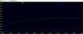
For example below is the simulation for three values of R1 (it's for you to determine what those values were).
It shows the trade-off between signal rise-time and ripple voltage.

1615272896096.png
 
Last edited:

ericgibbs

Joined Jan 29, 2010
18,849
Hi arhzz1.

Look ar this link regarding 50% duty cycle Mean value.
https://ch.mathworks.com/matlabcentral/answers/111916-find-the-voltage-from-a-pwm-signal

This Clip is the definition of Mean voltage:
The average or mean value of an alternating voltage or current waveform is its value taken over one half-cycle (or pulsating DC) otherwise the average value found over one full cycle of a sinusoid would be zero, as the identical positive and negative half-cycles cancel out,

Can you confirm with your Tutor what 'Mean value' the question refers too.?

E
 

ericgibbs

Joined Jan 29, 2010
18,849
hi C,
This is what you posted in one reply.
You need a corner frequency low enough to smooth the PMM pulse into a DC value with some small ripple voltage.
then
Is that different from what I said: filter to get the mean (average) value of the PWM signal?

I would debate, without knowing the acceptable level of 'ripple voltage', the question cannot have a definite answer

E
This is my interpretation of the question for the Mean/Average of the 50% duty cycle of a 3.3V PWM.


Attachments

MrAl

Joined Jun 17, 2014
11,486
Hello!

Just want to say that this is my very first time using LTSpice (I installed it 20 minutes ago),and I know that my questions are most likely trivial to people like you,but I'd like to learn so any guidance or help will be much appriciated.Now to the task

A pulse-width modulated square-wave signal should be filtered so that at output of the
Filter the mean value of the signal is present. The fundamental frequency is fPWM = 10 kHz.
This corresponds to a period of TPWM = 1 / fPWM = 100 µs.

1.Change the resistance and capacitance value so that the capacitor voltage
can no longer follow the input voltage. In the steady state
the maximum and minimum voltage value should be distinguished at the capacitance by a maximum of 100 mV
To do this, also adjust the simulation time. Which component do we need to use?

2.What happens if you change the tone in the voltage source and thus the duty cycle
(Duty cycle) of the PWM changes. Describe your observation.

3.Increase the filter effect by connecting another RC element between the voltage source and the resistor. Plot the voltage curve over both
Capacitors. What are you observing

Now for part 1. I tried simply finding how to build a generic filter in LTspice. I have done that like this (see attachment) but now I am not sure how to check if the capacitor voltage can no longer follow the input voltage.If I go to run and click on the capacitor I am getting the current (I) flowing through the capacitor.And to get get the value of the input voltage I have no Idea how to do.

Any help is appreciated! Thank you :)
Just some hints and ideas for approximations...

First, the RC time constant is an important criterion for a problem like this. The RC time constant can give you an approximation for calculating the ripple and the rise time.

I wont give the answers yet, but if you apply a single step wave to the RC filter you can calculate the rise time by knowing the time it takes for the output to change from 0 to 90 percent which is the usually accepted definition.
Secondly, you can calculate the small change in output with each pulse using a straight line approximation when the RC time constant is much longer than the pulse period, and that is always going to be the case when you are trying to get an average value output using just an R and C filter with no inductor or op amp.

So really these are both the same concept just one is over a longer period and one is over a very short period. The long period calculation really should include the exponential form but the short period calculation can use a straight line approximation which means a simple multiplication or division.

Another interesting point is that there will be a duty cycle (assuming constant frequency) that produces the highest output ripple. That would be the worst case scenario that you would want to investigate so that you can choose the RC time constant to meet the output ripply criterion.
For example, is it closer to 10 percent, 25 percent, 50 percent, 75 percent or 90 percent, where you get the highest level of output ripple. When you find that you will have the proper test duty cycle to make absolutely sure your filter will meet the given design spec.
If your design must also work with a variable frequency input, then you have to investigate what frequency input gives the highest value of output ripple and that will be the frequency you need to design for and test for. This should be easy to figure out because the lower the frequency the longer the output has to change.
 

Thread Starter

arhzz1

Joined Oct 21, 2020
50
Okay so after a lot of reading trying rince and repeating I've figured out most of it. Now what I needed to do for this problem is adjust the values of R and C in a way that the Voltages look like this.The problem was the settling time,the frequncy of 10kHz was to low for the values of R and C to be 50ohm and 200nF respectivly.Now I've a few dozen of combinations in regards of the values of R and C and come to conclusion that 1k Ohm and 1uF are pretty much what I need.I've determined this by simply trying,but not with an "educated guess".I would like to now what would be the way to calculate what the values of R and C have to be (precisly) or do you simply have to go by a hunch so to say.

Also the .asc file
 

Attachments

MrAl

Joined Jun 17, 2014
11,486
Okay so after a lot of reading trying rince and repeating I've figured out most of it. Now what I needed to do for this problem is adjust the values of R and C in a way that the Voltages look like this.The problem was the settling time,the frequncy of 10kHz was to low for the values of R and C to be 50ohm and 200nF respectivly.Now I've a few dozen of combinations in regards of the values of R and C and come to conclusion that 1k Ohm and 1uF are pretty much what I need.I've determined this by simply trying,but not with an "educated guess".I would like to now what would be the way to calculate what the values of R and C have to be (precisly) or do you simply have to go by a hunch so to say.

Also the .asc file
It is a matter of doing the two calculations i pointed out before, but because you are looking to average the result you will probably be more interested in the ripple and the settling time.

The settling time is the time it takes to reach an certain percentages of the change on the output. For example, if you what to find the settling time to be within 2 percent of the final (average) value then you would do a calculation for the average value and then do a calculation for the time it takes to get to within 2 percent of the final output value. if your output goes from 0 to 1v, then you want to solve for the time it takes to get to 0.98 volts. If the ripple is low then you can just use the exponential form and calculate the time from there. You can then reverse the formula so you are solving for R given a certain value of C such as 0.01uf, 0.1uf, 1uf, etc.

For the average you can often just use the straight line approximation. That involves the change in voltage when the pulse is high and the change in voltage when the pulse is low, and each has a certain time where it causes the change on the output.

Do you know how to do these calculations?
 

ericgibbs

Joined Jan 29, 2010
18,849
hi arhzz1,
As no level of the acceptable resultant ripple voltage on the 'Mean' has been stated in the question, I would say that filter is acceptable.
It is the settling time to the Mean level that is a governing factor in choosing the R C values.

E
This plot is using 50% of your C value, it is still acceptable.
Settling times 2mSec or 4mSec.
 

Attachments

Thread Starter

arhzz1

Joined Oct 21, 2020
50
It is a matter of doing the two calculations i pointed out before, but because you are looking to average the result you will probably be more interested in the ripple and the settling time.

The settling time is the time it takes to reach an certain percentages of the change on the output. For example, if you what to find the settling time to be within 2 percent of the final (average) value then you would do a calculation for the average value and then do a calculation for the time it takes to get to within 2 percent of the final output value. if your output goes from 0 to 1v, then you want to solve for the time it takes to get to 0.98 volts. If the ripple is low then you can just use the exponential form and calculate the time from there. You can then reverse the formula so you are solving for R given a certain value of C such as 0.01uf, 0.1uf, 1uf, etc.

For the average you can often just use the straight line approximation. That involves the change in voltage when the pulse is high and the change in voltage when the pulse is low, and each has a certain time where it causes the change on the output.

Do you know how to do these calculations?
Well that is kind of the problem,I'm not sure how to do the calculations.If you could post the formuals I need I'd think I'd be able to recognize what I need and do the necessary math.
 

MrAl

Joined Jun 17, 2014
11,486
Ok then let's start with the calculation for the average cap voltage. This is really just algebra.
Your challenge is to solve the final equation that results from some basic circuit concepts.

I will present this method because it is a general method for finding the average voltage without resorting to more complicated time equations and finding the simplified form of the mathematical series that results. It might appear to use calculus but that is kept to a minimum with only the definition of the capacitor required and there is no differential equation to solve nor any Laplace Transforms required. The 'dv' and 'dt' quickly become the increment forms which usually use the greek 'delta' symbol for the 'd' but i wrote it with a lower case 'd' for simpler typing. Maybe i'll type out the symbol form later (see far below for the two forms).

Refer to the drawing attached. In fact, you should really keep that drawing up on the screen as you read this because that will give you a good feel for how the math relates to the circuit.

Let E=V1, R=R1, C=C1, v=cap voltage, dv=change in cap voltage over short time spans, dt=small time increment, then the current in the cap is:
iC(t)=(E-v)/R

and the right side comes from the simple Ohm's Law, and when applying the cap voltage and current and time relationship we get:
C*dv/dt=(E-v)/R

and simply multiplying by C we get:
dv/dt=(E-v)/RC

where RC=R*C.
Now because we assume small time changes for t (which we call dt here) that means that v itself (the cap voltage) is considered constant (this would be the increment form not the true differential form and that would mean that we would normally see dv written with the 'd' as a greek 'delta' character).

Now because of the PWM the E value changes from the max voltage to the min voltage, and that usually means that E goes up to +Vcc and down to 0v, but be aware that it does not always go down to 0v sometimes it goes down to a smaller voltage like 1v and sometimes it goes completely open. If it goes to a lower voltage not zero we'd have to account for that, and if it goes open we would have to work this problem differently, but for now we assume that it does from some higher voltage liike 10v down to an actual 0v.

So going from where we left off and applying the TWO differnt voltage levels, that means we have two different equations, one for when the PWM is 'on' and one for whwen it is 'off'.
On: dv/dt=(E-v)/RC (no change)
Off: dv/dt=(0-v)/RC (replaced E with zero)

however when we short out E we noticed that the cap voltage is now considered positive, so we change that second one to have a positive cap voltage:
On: dv/dt=(E-v)/RC (no change)
Off: dv/dt=(0+v)/RC (replaced E with zero)

and of course a little simpler is:
On: dv/dt=(E-v)/RC (no change)
Off: dv/dt=v/RC (replaced E with zero)

Now we almost have to two expresions, but we see that the 'on' time dt is the same as the 'off' time dt and that is not the most general case. The most gereral case is that they are different, sl we just make each one unique:
On: dv/dt1=(E-v)/RC
Off: dv/dt2=v/RC

Now we multiply both sides by their respective time durations and we get:
On: dv=dt1*(E-v)/RC
Off: dv=dt2*v/RC

and the voltages changes might not be the same, but here we note from the darwing attached that when the voltage goes up it must come down by the same amount in order to hold the average. Thus, dv1=dv2 so ewe can leave those slone. Theoretically this is often referred to as "Continuity of States".

Now we could replace dt1 with the total period tp and the duty cycle or just use it as is. For now we will use it as is. Doing that we can still note that the two dv's are the same, so we can equate the two equations and get:
dt1*(E-v)/RC=dt2*v/RC

Ok now we would like to get the general expression for the average voltage as it relates to the duty cycle, and we note that if the 'on' time is a portion of the total time period (both on and off times) then the 'off' time must be the total time minus the 'on' time. In terms of the duty cycle, if the 'on' duty cycle is D then the 'off' duty cycle must be 1-D with D less than 1 (D is the fractional duty cycle like 0.50 for example).

This means that we can convert dt1 and dt2 through the use fo the duty cycle and the total time period tp as:
dt1=D*tp
dt2=(1-D)*tp

Now we just substitute these two into the two sides of that previous equation and get:
D*tp*(E-v)/RC=(1-D)*tp*v/RC

and now with v still constant we consider v to the the average cap voltage.

Ok so there you have the final equation to be solved for 'v' the average voltage, and the complete derivation,

Now you think you can solve that equation for 'v' the average cap voltage?
See what you can figure out and we can continue again after that. The result comes out so simple it may surprise you.

By looking at the waveform you will also notice that the entire wave curves, starting out sort of vertical and curving to horizontal. That curve is the exponential form we will talk about later and that provides the solution for the settling time.

PWM Averaging

Just the two cap forms i was talking about earlier:
TwoCapForms-01.png
 

Attachments

Last edited:
Top