Facebook
 Google
 GitHub
 Linkedin
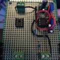
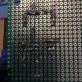
This is my 4th 555 timer construction with the same results. I used an NE555 twice and an LMC555 twice, both with consistent results and all purchased from Digikey. I am using a 12vdc regulated power supply. Schematic attached. Pin 3 will go to an optocoupler, but for testing purposes, I am using a standard LED. Target is 1Hz. I build the first ones on a breadboard using a 9v battery for convience and then move to soldering a perf board as the final. After the first two, I thought I may have over heated the timers, so I started using a DIP socket for the 555 and still got the same results. After my 4th Perf board, I decided to see what the results would be if I connected the 12v supply to the bread board, which was the only variable. I am using the Hz setting on a multimeter and visual for measurements.
These are the results;
Bread Board: 9v 1.02Hz Visual LED 1Hz Great Stuff !
12v 5kHz Visual LED 1Hz ???????
Perf Board: 9v 50Hz Visual LED constantly on
12v 5kHz Visual LED constantly on
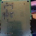
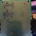
I soldered each perf board without referring back to the previous one and just focused on the schematic. I am now the proud owner of four perf boards that operate exactly the same.
Any thoughts would be appreciated.
These are the results;
Bread Board: 9v 1.02Hz Visual LED 1Hz Great Stuff !
12v 5kHz Visual LED 1Hz ???????
Perf Board: 9v 50Hz Visual LED constantly on
12v 5kHz Visual LED constantly on
I soldered each perf board without referring back to the previous one and just focused on the schematic. I am now the proud owner of four perf boards that operate exactly the same.
Any thoughts would be appreciated.
Attachments
-
 83.7 KB Views: 17