 Facebook
 Google
 GitHub
 Linkedin
Right,
Before the girlfriend takes over the weekend, here's my findings with sghiotos circuit in post 11.
Before the girlfriend takes over the weekend, here's my findings with sghiotos circuit in post 11.
Attachments
-
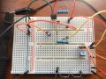 249.8 KB Views: 4


