 Facebook
 Google
 GitHub
 Linkedin
Hello out there.
I'm looking for a bit of assistance. I've been messing with a new project for the car. I'm trying to make a courtesy light dimmer from scratch as none of the pre-made stuff out there will suit my purpose. I'm aiming for making a PCB which i can enclose into a standard automotive relay shell and plug into the car as a plug and play item. There is a specific relay holder connection in play already, which i want to retain as is.
I've gotten quite far in, as I found a circuit online (in fact i found a few, but i've concentrated more on one, and had good results from it), but i have TWO problems. It's these two problems i'm hoping someone can help me wriggle free from.
PROBLEMS:
1. The LED's NEVER EVER fully go out, no matter what i try. If i put the ground path resistances up to high, so as to limit the drain current clearly keeping the LED's lit that little bit, then the circuit stops working properly.
2. The vehicle standard wiring has two diodes in circuit which stops cross contamination of other parts of the vehicle wiring and it's through these two diodes where the door switch completes the ground path for when the door it opened to make the courtesy lights come on. If i take these diodes out of circuit, the project works (all be it not fully putting the LED's out at the end of the dim operation), but with the diodes in play, the lights only go on and off according to door open/closed, and there is never any dimming!? I can't figure out why this is at all!? I obviously cannot remove these diodes, so i have to somehow work around this issue too.
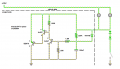
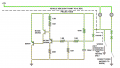
This is the circuit i have so far, but to be fair, if someone has a better one which they think will be better for my solution, then i'm open to changing tact no problem.
I made this video demonstrating what i've got (all be it for another audience than here) so maybe this will be of some use to demonstrate first hand...
I'm looking for a bit of assistance. I've been messing with a new project for the car. I'm trying to make a courtesy light dimmer from scratch as none of the pre-made stuff out there will suit my purpose. I'm aiming for making a PCB which i can enclose into a standard automotive relay shell and plug into the car as a plug and play item. There is a specific relay holder connection in play already, which i want to retain as is.
I've gotten quite far in, as I found a circuit online (in fact i found a few, but i've concentrated more on one, and had good results from it), but i have TWO problems. It's these two problems i'm hoping someone can help me wriggle free from.
PROBLEMS:
1. The LED's NEVER EVER fully go out, no matter what i try. If i put the ground path resistances up to high, so as to limit the drain current clearly keeping the LED's lit that little bit, then the circuit stops working properly.
2. The vehicle standard wiring has two diodes in circuit which stops cross contamination of other parts of the vehicle wiring and it's through these two diodes where the door switch completes the ground path for when the door it opened to make the courtesy lights come on. If i take these diodes out of circuit, the project works (all be it not fully putting the LED's out at the end of the dim operation), but with the diodes in play, the lights only go on and off according to door open/closed, and there is never any dimming!? I can't figure out why this is at all!? I obviously cannot remove these diodes, so i have to somehow work around this issue too.
This is the circuit i have so far, but to be fair, if someone has a better one which they think will be better for my solution, then i'm open to changing tact no problem.
I made this video demonstrating what i've got (all be it for another audience than here) so maybe this will be of some use to demonstrate first hand...
Attachments
-
 51.5 KB Views: 45


")


