Counter Circuits for All-Transistor Digital Clock

Thread Starter

Sensacell

Joined Jun 19, 2012
3,444
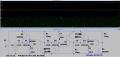
The first digit board is done!

It's a 10-stage discrete ring counter and diode matrix to drive the MINUTES display.
Students are getting some epic prototyping and soldering experience here with the hybrid SMD and thru-hole parts.


ring_counter.jpg

The LED filament segments are going to be mounted in a 3D printed frame, seen in Fusion 360 CAD here.

Display.png
 

MisterBill2

Joined Jan 23, 2018
18,475
I find the success with stair-step dividers very impressive. Those used to develop the timing for TV pictures back in the tube days did not use so many steps. And making one work with 60mV steps is awesome! I am glad that a suggestion worked out so well for the class project. It might be very entertaining to run this circuit on simulator software and watch the stair-steps.

Thanks for the update!
 

MisterBill2

Joined Jan 23, 2018
18,475
This is indeed an awesome project. And I am very impressed that you made the stairstep dividers work, since they were mostly used in the tube era. If the digit counters are ring counters there is another thread around where they would really benefit from seeing a working ring counter circuit.
AND thanks for the video!
 
@Sensacell
Nicely done.
Not exactly 60's technology. LED's in the 60's? SMT in the 60's.
The connectors probably didn't exist either or the breadboards.
It's Like "Nixie tube" "LED 7-segment display" which is an interesting concept.
What was the cost estimate for parts only? never seen those type of bulbs in the US.
 

MisterBill2

Joined Jan 23, 2018
18,475
So I got bored and decided to see if I could do the counter differently (design exercise). Heres my version:
Another variation of the classic stairstep divider. I caution you that the accuracy of the division is critically dependent on the component value accuracy and stability. But it is indeed quite impressive.
 

iimagine

Joined Dec 20, 2010
511
I caution you that the accuracy of the division is critically dependent on the component value
Yeah, I'm suspecting those caps in the nF value range are not gonna hold. If I was to build it, I would use larger caps in the uF range. Other then that, I dont think anything else is critical.
 

MisterBill2

Joined Jan 23, 2018
18,475
Yeah, I'm suspecting those caps in the nF value range are not gonna hold. If I was to build it, I would use larger caps in the uF range. Other then that, I dont think anything else is critical.
The stairstep circuit depends on charge pumping and so really most of the circuit elements are rather critical. But with your simulator it would be easy to experiment with changing part values to see which parts are the most critical.
 

Thread Starter

Sensacell

Joined Jun 19, 2012
3,444
The stairstep circuit depends on charge pumping and so really most of the circuit elements are rather critical. But with your simulator it would be easy to experiment with changing part values to see which parts are the most critical.

There must be some "trimmable" components in real-world design, it's not practical without this feature, unless the division ratio is really small, like 3 or 4.
 

MisterBill2

Joined Jan 23, 2018
18,475
There must be some "trimmable" components in real-world design, it's not practical without this feature, unless the division ratio is really small, like 3 or 4.
The solution, back in the time when vacuum tubes were the active elements of stair-step dividers, was to make the steps larger to the point that component variations and drift did not cause problems. That meant that more stages would be used, but the benefit was that the stability and reliability were improved. So instead of a divide by 60 stage, there was divide by 3,4, and 5, giving the same results with much larger steps. And still it was much simpler than using flipflops and a decoder.
 
Top