 Facebook
 Google
 GitHub
 Linkedin
I have been given a homework question, with two parts.
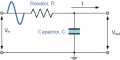
Part one to use theory and calculate the corner frequency of a passive low pass RC filter.
Such as this:

Fairly easy to understand being,
\[ f_c = \dfrac{1}{2\pi R_1 C_1} \]
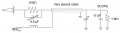
However the second part of the question, was as though I tested it in the lab, and that i noticed the corner frequency was no what it should have been.
As far as I can tell in this situation this would have been due to the passive probe and the scope its self, as per An Introduction to Oscilloscope Probes. With the possibility of the probe being set to x10, or the compensation capacitor affecting the reading.
Reading the datasheet for the 2204A, it has a 1M Ohm || 14pF input characteristic. However I am unsure of two things
1. The standard probe that comes with the 2204A, so I can get the compensator capacitor and other data from it. and
2. How to this include this additional resistance and capacitance to calculate the corner frequency if including these elements.
Part one to use theory and calculate the corner frequency of a passive low pass RC filter.
Such as this:
Fairly easy to understand being,
\[ f_c = \dfrac{1}{2\pi R_1 C_1} \]
However the second part of the question, was as though I tested it in the lab, and that i noticed the corner frequency was no what it should have been.
As far as I can tell in this situation this would have been due to the passive probe and the scope its self, as per An Introduction to Oscilloscope Probes. With the possibility of the probe being set to x10, or the compensation capacitor affecting the reading.
Reading the datasheet for the 2204A, it has a 1M Ohm || 14pF input characteristic. However I am unsure of two things
1. The standard probe that comes with the 2204A, so I can get the compensator capacitor and other data from it. and
2. How to this include this additional resistance and capacitance to calculate the corner frequency if including these elements.
Attachments
-
 6.9 KB Views: 5
 -
 16.6 KB Views: 5


