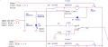
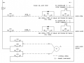
Coop door opener with 2 way 12VDC motor

MaxHeadRoom

Joined Jul 18, 2013
30,871
Many times a default value is used because it will often work and cover most bases.
Confirmation of operation can also be made with the actual model.
Max.
 

tracecom

Joined Apr 16, 2010
3,944
TY MAx,
to the original queastion, though (#91) - and for my curiosity - why, in the schmatic, is it necessary to have a 1k ohm resistor in front of a transistor which is only receiving 5VDC and 30mA from the MC? Wouldn't the low output of the MC be small enough to drive the transistor without harm?
Here's a non-engineer's explanation. The output from your microcontroller is not supplying 30mA; it is supplying whatever current is allowed by the circuit attached to it. Now, maybe that particular uC has built-in protection from supplying more current than it's rated for, but just in case it doesn't, the 1k resistor limits the current to about 5mA, which is enough drive the 2N2222 fully on. Then, the 2n2222 (supposedly) supplies the current required to operate the relay (which I haven't calculated.) In a worst case scenario, your uC doesn't have any built-in protection against sourcing excessive current, and the 2N2222 goes short to ground; at that point, your uC releases the magic smoke if the 1k resistor isn't there to limit the current.
 

Thread Starter

rfeyer

Joined Aug 24, 2014
126
That I actually understood - TY tons!
This may be an insane question: but, but a diode protect as well instead of the transistor? I am not replacing the transistor, just asking hypothetically.
 

Reloadron

Joined Jan 15, 2015
7,975
That I actually understood - TY tons!
This may be an insane question: but, but a diode protect as well instead of the transistor? I am not replacing the transistor, just asking hypothetically.
If we look at the data sheet for a 2N7000 N-Channel Enhancement Mode Field Effect Transistor we see that there is a diode included right inside the case. That diode we see in there across the Drain and Source is in there for protection. :)

Ron
 

shortbus

Joined Sep 30, 2009
10,049
If we look at the data sheet for a 2N7000 N-Channel Enhancement Mode Field Effect Transistor we see that there is a diode included right inside the case. That diode we see in there across the Drain and Source is in there for protection. :)

Ron
Ron, this is misleading, or at least it has been to me in the past. It has/was in the past been stated many times and places that the internal diode in a mosfet is an "artifact" of the mosfet making process and not to be counted on for any of the values listed in the rest of the data sheet. Meaning if the mosfet is rated at, 'X' volts and 'Y' amps the diode is not the same value. Or has this now changed or been debunked? Seeing more and more people on the forums saying to just count on the internal diode and no need to add a discreet one to the circuit.
 

tracecom

Joined Apr 16, 2010
3,944
That I actually understood - TY tons!
This may be an insane question: but, but a diode protect as well instead of the transistor? I am not replacing the transistor, just asking hypothetically.
If you mean replace the resistor with a diode, no. The diode would provide a small voltage drop, and protection against a reverse polarity connection, but would not limit the current like a resistor.
 

Thread Starter

rfeyer

Joined Aug 24, 2014
126
TY - That helps as well - I realize I will have to do a lot more HANDS ON after this project is done. It starts making sense when you put things together, and when you realize where you made mistakes (found another wiring mistake).
Am also checking into schematic/ diagram programs which will reduce the time I spent on using MS Paint, cutting pasting, etc, etc, :)
I will have to re-read this whole thread and extract all the points made before I forget them
Amazing help from everyone, truly!

Rainer
 

Thread Starter

rfeyer

Joined Aug 24, 2014
126
About ready to put the board to the test - rechecked wires and came up with power supply.
I hopefully have my last ignorat question about this particular project:
The MicroController has a 5V 30mA output which we are using to stimulate the transsiter which then allow to run a 12V 5+A ciruit through the collector/ emitter.
here is the question:
Where do I return the circuit to the ground of the MC? If I tie intot he ground of the post-transistor circuit, would that not be too much voltage and amperage? Would I simply place a 10k resistor into the return?
here is the current schematic:
upload_2015-2-14_9-34-49.png
 

Reloadron

Joined Jan 15, 2015
7,975
Ground is ground, your uC shares the same ground as the entire motor circuit. As to the 5V 30mA, that simply means the uC can source 30mA, not that 30mA will be applied or used. The 1K base resistors limit the base current on the transistors. My guess was the relay coil will draw about 150 to 200mA. Likely around 150mA. All said and done, this is not an exacting science, a base resistor between 500 and 1,000 Ohms should ensure we drive the transistor into saturation making for a good switch.

So all commons or grounds are common to each other, the uC and controller circuits and don't worry about the 1K resistors or 5 volts to the transistors. If you want, just apply 5 volts to each resistor and see if the relays click. :)

Ron
 

Alec_t

Joined Sep 17, 2013
15,160
Ground is ground, your uC shares the same ground as the entire motor circuit.
However, you must ensure high motor current doesn't pass through thin conductors and cause a voltage drop which might affect the MCU. Read up about 'star grounds'.
 

Reloadron

Joined Jan 15, 2015
7,975
However, you must ensure high motor current doesn't pass through thin conductors and cause a voltage drop which might affect the MCU. Read up about 'star grounds'.
Oh yeah, you may want to give that a read. For your case make sure the main motor power is all handled by AWG12 cable. Battery to relay to motor terminals. Alec brings up a good and important point as you get ready to run and test.

Ron
 

Thread Starter

rfeyer

Joined Aug 24, 2014
126
TY both!
Another interesting read so far. And being amazed!
I was under the impression, when I layed out the wiring of my little board, that I should NOT connect all returns at the same area which goes to ground - simply, when I was reading about connecting mutiple temperature sensors it was highly disregarded to connect to a central source (though it did not mention anything about central return).
So, I automatically ASSUMED that it would not be good to have a star ground.
Thanks again, will keep reading.
Rainer
 

Thread Starter

rfeyer

Joined Aug 24, 2014
126
I don't know if this is amusing, but here it goes:
Attached the power to the circuits and, when powering the LOWER portion, the relay clicks but there is no power tot he motor (does not register any amount of voltage).
When I power the RAISE portion, the motor runs on an on off cycle, very regularly, at about 1 second go, then stop, then go, then stop.

If someone's light goes on and says: "I know what this is" then great, if not, I will buy more components and start again.

Rainer
 

Thread Starter

rfeyer

Joined Aug 24, 2014
126
FlareGuy,
TY tons for the schematic, but, I haven't a clue what it means :(
I do seem to understand Ron's schematic, and have tried to adopt it, but have the above problem of a pulsating output.
A new schematic is not going to the route I wish to take, thanks.
As Ron, Max and others can attest, I am greener than green in electronics, and older in age as well. So, i am somewhat familiar with usual schematic symbols of transistors, diodes, relays, even some of the IC's I've been reading about, but the above I cold not name anything familiar, other than the motor and diodes :)
 
Last edited:

Thread Starter

rfeyer

Joined Aug 24, 2014
126
OK - About to solder another board - hopefully a bit more organized - using a Unviersal board such as suggested by Max.
I have it pretty much all drwan out - hopwever, one question:
The MC will input a 5V ~30mA intput to raise or lower the unit.
Am I correct that the ground/ negative return can come form the same negative/ ground bus which is on the board used for the rest of the circuitry?

Rainer
 

MaxHeadRoom

Joined Jul 18, 2013
30,871
Yes, I think post #109 touched on that.
In some case where a higher voltage component such as a DC motor is used and switch by relays, the commons can be kept separate.
Not sure if this thread touched on it earlier but makes sure motor current does not return through the control conductors or the common/(ground) portion of the board where low voltage control exists.
Max.
 

Thread Starter

rfeyer

Joined Aug 24, 2014
126
Aging on my part - TY MAx,
tought it was answered but wanted to make sure.
Again, I need to make a summary of all the great points answered on this!!

Rainer
 
Top