Converting an analog PLL into its digital equivalent

Thread Starter

ak52

Joined Oct 15, 2014
230
Hello Everyone,
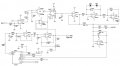
Attached is a reference anaog PLL circuit which we are currently using,i would like to optimise the circuit and implement it into a microcontroller.
The above circuit is very stable and the output sine wave locks perfectly with the input.
How would i approach such a thing?

Thanks in advance
AK

PS: forgot to attach the circuit!
 

Attachments

Papabravo

Joined Feb 24, 2006
21,159
I would start by learning about DDS (Direct Digital Synthesis). There will be a whole new class of problems to deal with in this digital NCO(Numerically Controlled Oscillator).
 

Thread Starter

ak52

Joined Oct 15, 2014
230
I would start by learning about DDS (Direct Digital Synthesis). There will be a whole new class of problems to deal with in this digital NCO(Numerically Controlled Oscillator).
What kind of problems,i forgot to mention i dont really need to have the output converterd back into a sine wave(so no DAC required),if i could just store the values in an array,that will be good enough.

A few points which i have been researching on and need some help:
Since the above circuit is completely analog,the sampling is continuous ,if i use a MCU(ADC) then the input sampling is digital,what can be the maximum acceptable delay ,which does not effect the stability out the PLL output.
Also if i can have an additional functionaly to choose the frequency locking range ,that would be very useful.
 

Papabravo

Joined Feb 24, 2006
21,159
When you move from the analog domain to the digital domain the problem of aliasing causes the frequency domain to fold back on itself and produce unwanted images.
In order to have a loop you have to have an output which is compared with a reference input. I can't quite get my head around how you would do that or even see the effects by putting numbers in an array.
Checkout this tutorial from Analog Devices

http://www.analog.com/media/en/training-seminars/tutorials/MT-085.pdf
 
Top