Tracecom and I were wondering if you were still alive. Fortunately, I won the bet.
Before going much farther, do you simply want to demo the circuit on a breadboard or are you planning to make the project permanent? A breadboard is great for prototyping, not so much for long term use though. You can certainly do both, but as funds sound tight, maybe you want to jump to making a permanent board? If you opt to breadboard first (strongly suggested), you'll probably spend ~$20-$30 USD for a nice big one with plenty of space. A nice stripboard to make your circuit permanent and put into your light will run ~$5-$10 USD. Tell us how you'd like to proceed and I'll make some suggestions.
No soldering is needed for breadboarding, but you will need jumper wires. When making a permanent circuit, you'll need solder and a soldering iron.
I didn't include a power jack as I wasn't sure what power supply you'd be using. Can you send a spec or post some pictures of your power supply, specifically the label and the output tip.
Doh, just checked my BOM - assuming you're using the power supply called out there, this will work. If you don't have a need to order anything else from Digikey and you're close to a RadioShack, this, this, or this will work.
For use on a solderless breadboard, the best I have found are just short pieces of 22AWG plated solid wire. Because I do a lot of breadboarding, I bought six different colors of wire, and I cut three different length pieces and strip about 3/16" of insulation from both ends. I use red for +V, black for ground, and the other four colors for signals. The different colors make it much easier to follow the circuit. You can buy premade jumpers, but they don't work as well for me as the ones I make from this.
Tracecom makes an excellent suggestion and it is certainly the least expensive option given the total length/number of jumpers you can make.
There are two types of jumpers, fixed length and loose/flexible. These are simply arbitrary names I made up. The fixed length can be made from solid core wire or bought premade. The premade option comes with straight wires in specific lengths great for breadboards when making connections between IC and components. The loose/flexible variety are typically longer and are often made from stranded wire in longer lengths when you need to make connections across a long distance on or off the breadboard or there is not enough room on the breadboard to run fixed lengths. Again, these can be made or bought.
Any other suggestions? I put my last digikey and sparkfun orders on hold for this to save on shipping. Breadboard and jumpers are ordered. Also, I assume I need a place to plug-in my picaxe programming cable. That would require something like this: http://www.picaxe.com/Hardware/Starter-Packs/PICAXE-20-Starter-Pack/ right?
For switches, take a look at this (black) and this (red) from Digikey. Just found a four pack at RadioShack for $4 USD.
Which programming cable do you have? Is it this one? If yes, all you need is something like this.
While ordering parts, you may consider ordering a prototyping board for your final assembly such as this. If you do, you may want to order some IC sockets for the ICs as well. Up to you though.
Some parts are shipped, sparkfun is taking its time shipping its end of the deal.
With the psu - I assume that the barrel connector tracecom recommended has a +, -, and ground pin which I connect via jumper wire to the parts on the breadboard? Am I far off?
Also, looking at the schematic, I see that the power module is all on its own (i.e. no connections to any parts on the rest of the modules), so there's something I'm missing here right?
I'm going to have lots of questions as I assemble this. Connecting the pins to the various chips makes sense to me, it's the power aspect as well as the resistors/capacitors that sort of mess with my mind. I think I understand they are to make sure each component gets the right amount of electricity so they don't go poof - right?
With the psu - I assume that the barrel connector tracecom recommended has a +, -, and ground pin which I connect via jumper wire to the parts on the breadboard? Am I far off?
I'm not sure which connector you are referring to. In any event, you'll want to plug in the PSU and use a volt meter to determine which pin from the connector is + and which is -. The PSU only outputs 5VDC, so there is only + and -, no dedicated GND, though I always refer to - as GND in DC circuits.
Also, looking at the schematic, I see that the power module is all on its own (i.e. no connections to any parts on the rest of the modules), so there's something I'm missing here right?
Which schematic are you referring to? Tracecom includes a power circuit that allows you to use a PSU with a voltage rating anywhere from about 7 to 30VDC. The output (5VDC) is then connected anywhere you see 5VDC in the circuit.
If you're using a 5VDC regulated PSU, you don't need an additional power circuit as it's all done in the PSU. On hindsight, that is why I selected that PSU. I try to minimize parts count when I can.
Connecting the pins to the various chips makes sense to me, it's the power aspect as well as the resistors/capacitors that sort of mess with my mind. I think I understand they are to make sure each component gets the right amount of electricity so they don't go poof - right?
Capacitors and resistors serve a number of functions, but in this circuit they serve very simple roles. Nearly all the resistors serve as either pull-ups or pull-downs. These provide a + or - voltage to the pins of the ICs so that the IC's know if there is a signal or not. This prevents the inputs from "floating" and the ICs from acting randomly. The capacitors are simply used to filter electrical noise, also with the goal to help prevent the ICs from acting randomly.
Okay, so the last parts finally arrived today! (Darn Sparkfun took 4 days to ship! ) and I begun some very (very) rudimentary construction. I wanted to start simple, so I tried to get the PICAXE hooked up to the PC. Attached is my (very bad) circuit. What I know so far is that I got some part of the power part right, since the PICAXE is getting warm. Unfortunately, I messed something up with the breadboard adapter part because the PC isn't connecting (all the USB driver nonsense I took care of, so I'm pretty sure it's not that). Now I know ideally I need to solder some of those connections, but I figured it would at least work as long as everything has continuity with what it should - something went wrong. But what?
I am ordering a soldering kit to do those bits up more cleanly (and getting some alligator clips because my power connection is a little bit hmm...loose?
No, nothing is touching the blue rail, it is just sitting atop that space. I think what's happened is that all the pins aren't hitting with the breadboard adapter and not getting continuity. What I'm hoping elec_mech or tracecom can tell me if I have the pins set up in the right order coming from the PICAXE to the adapter.
Sorry, I found the datasheet on the breadboard adapter yesterday, but didn't have a chance to study it until today.
Alrightly, first, you're correct, you must solder the resistors and SIP pins (pins that allow board to plug into breadboard). You cannot rely on the hope that they'll make contact and stay that way otherwise.
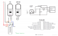
You don't need 8 pins, only four (three really). You just need to solder four in one of the rows, not both. I assume each row is connected to one another, but you might want to use a meter and perform a continuity test first. To clarify, remove all pins from the end of the board and use a meter to see if there is continuity between the two holes next to 01, then IN, then 02, then 0V. If yes, then I suggest soldering a row of pins in the row of holes closest to the edge of the board. This way you can connect the board to the edge of the breadboard in case you need the space.
Once the board is soldered and mounted to your breadboard, keep the jumper where it is on the board (closest to 01) and connect the 01 pin to pin 19 on the PICAXE. Connect the IN pin to pin 2 on the PICAXE. Connect 0V to GND as you've shown in your picture. This should allow your PC to communicate with the PICAXE now. Be sure there is 5VDC across pins 1 and 20 of your PICAXE. Pin 1 should be +, pin 20 should be -/GND.
Once the board is soldered and mounted to your breadboard, keep the jumper where it is on the board (closest to 01) and connect the 01 pin to pin 19 on the PICAXE. Connect the IN pin to pin 2 on the PICAXE. Connect 0V to GND as you've shown in your picture. This should allow your PC to communicate with the PICAXE now. Be sure there is 5VDC across pins 1 and 20 of your PICAXE. Pin 1 should be +, pin 20 should be -/GND.
Thanks everyone for the help. Today I got a little soldering kit and did some practicing. I even made a little circuit of flashing LEDs and a siren (thanks to a fun little starter kit).
After that I revisited the real circuit and followed your instructions and those from the kit, making sure to solder the resistors, the stereo connector, and the 4 pins. (Then I added some alligator clips to make it a bit more elegant. I put everything together then tried to connect but no dice! The thing is still telling me there is no connection, check power/connection.
(On a side note, I've soldered more this past week than ever doing this and working on the electrics to a motorcycle I am learning how to rebuild - funny how that works [and I need more spare time to work on these addictive hobbies!])
Looks like it is connected properly. Have you verified +5VDC is going to pin 1 and GND is going to pin 20?
Set your meter to VDC (if there are multiple options, turn it to 20VDC). Place the red probe to pin 1 on the IC and the black probe to pin 20. Do you see 5VDC or -5VDC? If the latter, the power connections from the supply to your breadboard need to be reversed.
Make sure the power supply is plugged in and power is going to your IC before you try to establish a connection with the PC.
I would suggest that you get into the habit of using wire colors consistently whenever possible, especially for power and ground. For example, I try to always use black for ground and red for +V; that way, I can tell at a glance "what's hot and what's not."
And trim those leads on the bottom of the PCB; they are just asking to short something out.
But most of all, congratulations on getting started!
 Facebook
 Google
 GitHub
 Linkedin