Converting a Rotary Switch to Simple On-Off

Thread Starter

AK1

Joined Oct 22, 2015
13
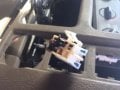
My windshield had a leak and some water dripped onto the dash causing my rear AC control switch to malfunction.

A new rotary switch is $50, which I don't want to buy. I'd like to get a simple toggle switch off Amazon.

The current rotary has 4 positions High-Med-Low-Off. I'd like the toggle to switch between High and Off.

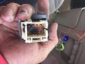
Currently, there are 6 pins, 4 brown, one grey, and one black.

QUESTION: Can I buy a 3 pin toggle and hook up the grey, black, and brown that controls High and just cap the remaining 3?
 

Attachments

crutschow

Joined Mar 14, 2008
34,201
Don't quite understand why there are more than four wires, so until that's understood I'm not sure how to connect the new switch. :confused:
Are two of them to illuminate the switch?

Note that you could likely use a SPDT switch with center off to give you at least two speeds.
 

Thread Starter

AK1

Joined Oct 22, 2015
13
Don't quite understand why there are more than four wires, so until that's understood I'm not sure how to connect the new switch. :confused:
Are two of them to illuminate the switch?

Note that you could likely use a SPDT switch with center off to give you at least two speeds.
I was under the impression there was one brown wire for each rotary position (Off, Low, Med, High) along with the additional two for positive and negative.
 

crutschow

Joined Mar 14, 2008
34,201
I was under the impression there was one brown wire for each rotary position (Off, Low, Med, High) along with the additional two for positive and negative.
Normally the negative is provided by connecting the fan to the vehicle frame and doesn't come from the switch.
 

Thread Starter

AK1

Joined Oct 22, 2015
13
Normally the negative is provided by connecting the fan to the vehicle frame and doesn't come from the switch.
Interesting. Also, the switch does illuminate when the headlights are engaged or the light sensor clicks them on.

I guess ill just test a 3 pin and see what configuration works.
 

crutschow

Joined Mar 14, 2008
34,201
the switch does illuminate when the headlights are engaged or the light sensor clicks them on.
Which would indicate that two of the wires are for the switch bulb, leaving 4 wires for the fan, as I would expect.

Here's an example of an automotive type SPDT center-off switch that could be used to give you two speeds for your fan.
 

Thread Starter

AK1

Joined Oct 22, 2015
13
Which would indicate that two of the wires are for the switch bulb, leaving 4 wires for the fan, as I would expect.

Here's an example of an automotive type SPDT center-off switch that could be used to give you two speeds for your fan.
Ok, I got this:
The rear heater and air conditioning (A/C) functions are controlled by the rear heater switch and the rear A/C switch respectively. The battery voltage is provided to the rear heater-A/C relay (rear) coil by the HTR-A/C fuse 12 and CKT 141 (BRN). The coil is grounded by CKT 850 (BLK) cavity B9 of the rear heater-A/C relay (rear). The rear heater-A/C relay (rear) is energized when the ignition switch is in the RUN position. The rear-A/C relay (rear) provides the battery voltage to the rear heater switch and the rear A/C switch. The RR HEAT/ A/C fuse provides battery voltage to CKT 1040 (ORN) cavity A9. Cavity A9 is the common contact of the rear heater-A/C relay (rear). The common contact and the normally open contact are connected when the rear heater-A/C relay (rear) is energized. The connection provides voltage to CKT 1923 (ORN) cavity B7 of the rear heater-A/C relay (rear). The rear heater-A/C relay (rear) supplies the voltage to the rear heater and the rear A/C switches.

The blower speeds are controlled by the rear A/C switch for the rear A/C blower motor. CKT 1923 (ORN) provides the battery voltage to the rotary contact of both of the switches. The full current flow is provided to the following circuits when either switch is in the HIGH position:
CKT 1052 (ORN) for the rear A/C
The motor is grounded through CKT 1250 (BLK). The motor will operate at full speed when the motor is grounded.

Limiting the current flow through the rear A/C blower motor results in slower blower speeds. Place resistance in the current path for the rear blower motor in order to limit the current flow. A current path is provided through the following route:
CKT 1072 (LT BLU) cavity A for the A/C

Through the rear A/C resistor pack connecting through the respective motor.
The blower switch is placed in the LOW position in order to attain a lower speed. Lowering the speed provides a current path through the following items:

CKT 1176 (YEL) (A/C)
Cavity C of the resistor pack
The circuit is then completed through the resistor connector to cavity C and the resistor connected to cavity B.

This places 2 resistors in the current path. The current to the motor is reduced more when the 2 resistors are in the current path.

When the heater A/C control valve solenoid is energized heated engine coolant is provided to the rear heater core. The solenoid is powered by a second set of contacts in the rear heater switch. Battery voltage from CKT 1923 is provided through the following switch positions:
HIGH
MED
LOW
These positions provide battery voltage from CKT 1596 (GRY/BLK) through the convenience center to the heater A/C control valve solenoid. The solenoid is grounded at CKT 850 (BLK). The solenoid will be energized when the solenoid is grou
nded.

Turns out the exposed wires I saw initially were just heat faded.

I have a 3 pin automotive rocker switch (waiting on the SPDT) and I'm trying to figure out how to wire it now... The description says that it will blow on HIGH if its grounded. I attempted (black, grey, blue) and (black, grey, yellow) but it didn't work.
 

Attachments

Top