Converting 3.7 v D.C. to 110 v A.C - Portable.

Thread Starter

Dan91

Joined Jul 6, 2022
5
Hello All. This is my first post here and i'm sorry if i'm posting in the wrong section but i am wondering if anyone is able to help.

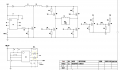
My end goal is for the PCB to convert 3.7 DC into 100 AC. the input will be using a 1500 Mah LI-PO battery and the output will be to power EL wire. with three settings. On / Off / Pulse.

ill be using 4 meters of EL wire. but i think something has been very lost in translation because they said the 4 meters will be 1040 watt. surely this is wrong??

My basic knowledge of design only got me so far before i asked a friend to help (who then asked another friend.) iv been sent this diagram and quite frankly im not sure what im looking at or even if this is the best solution. size of the PCB is important because it needs to be portable.

If anyone could offer any help or advice id be really grateful.

Thanks
Dan.
 

Attachments

ronsimpson

Joined Oct 7, 2019
3,037
1040 watts = 100 volts x 10 amps.
1040 watts = 3.7 volts x 281 amps. Your battery will be used up in about 1/3 second.
I think your little battery should not run more than 4 watts of power not 1050 watts.
 

Papabravo

Joined Feb 24, 2006
21,225
What you are looking at for the moment is a fantasy pipe dream. A schematic template with no component values is as useless as a screen door in a submarine. Tell your friend to get off his lazy butt and give you something you can actually utilize. I'd almost be willing to call your friend a fraud for trying to dazzle you with bullshit

Basically, what the template is showing is a boost converter followed by full bridge inverter. The devil with both of these circuits is in the details and those are sorely lacking.

First principles: the immutable rule of all power conversion schemes is this:
The power out will always be less than the power in. Sometimes it will be a great deal less.

I'd be interested to know if you have any idea what power is available from a 3.7V Battery. Let us say for the sake of argument that it is 5 Watts. That means the available current would be 1.35 Amperes. Now assuming the scheme was 100% efficient 5 Watts at 100 V is 50 mA, which is not much when it comes to powering an AC load.

How about you tell us what you want to use this power converter for, and we can guide you to a solution or convince you to adopt more realistic goals.
 

Jon Chandler

Joined Jun 12, 2008
1,051
I think you need to do some research on the power requirements of EL wire. A little research found 4+ meters that operate from power supplies with two double-A batteries. Seems that you're off by several orders of magnitude.
 

Thread Starter

Dan91

Joined Jul 6, 2022
5
What you are looking at for the moment is a fantasy pipe dream. A schematic template with no component values is as useless as a screen door in a submarine. Tell your friend to get off his lazy butt and give you something you can actually utilize. I'd almost be willing to call your friend a fraud for trying to dazzle you with bullshit

Basically, what the template is showing is a boost converter followed by full bridge inverter. The devil with both of these circuits is in the details and those are sorely lacking.

First principles: the immutable rule of all power conversion schemes is this:
The power out will always be less than the power in. Sometimes it will be a great deal less.

I'd be interested to know if you have any idea what power is available from a 3.7V Battery. Let us say for the sake of argument that it is 5 Watts. That means the available current would be 1.35 Amperes. Now assuming the scheme was 100% efficient 5 Watts at 100 V is 50 mA, which is not much when it comes to powering an AC load.

How about you tell us what you want to use this power converter for, and we can guide you to a solution or convince you to adopt more realistic goals.

Hi, Thank you for the fast reply.

Yes i appreciate that without vales of the components its very hard to actually see whats going on.

Im trying to power 4 meters of EL wire.

I have a PCB that can power 1 meter with a 3.7 DC and its a 300 mAh battery.
all i am trying to do is scale up to power 4 meters.

The photograph attached is the PCB that was used to power the 1 meter length.

/Dan
 

Attachments

Thread Starter

Dan91

Joined Jul 6, 2022
5
I think you need to do some research on the power requirements of EL wire. A little research found 4+ meters that operate from power supplies with two double-A batteries. Seems that you're off by several orders of magnitude.
Right i agree. thats why i thought it was completely wrong when they said 1040 W - im guessing they actually meant 1040 mW.
 

Thread Starter

Dan91

Joined Jul 6, 2022
5
My Apologies. sorry i said EL wire. its EL tape.

2 centimeters wide times 130 centimeters long - and i will have 4 of these.
Different searches come up with different answers. but the gentleman in the factory swears its 2 watt per Cm2

Ill check the resistance shortly. - Thank you.
 

djsfantasi

Joined Apr 11, 2010
9,163
EL wire or tape is driven by AC… And I think the 1040W figure is wrong. All the EL inverters I’ve seen are driven by AA batteries.
 
Top