Converting 24VAC Halogen SCR Dimmed Fixture to LED

Thread Starter

Tim Davis

Joined Jun 10, 2015
23
I did try the warm white bulb, I noticed that the old one was actually 80W and this one is 100W. Can't really do much testing with the flickering and lack of heat sink so far. ( Will do later) but I notice after 70% it doesn't get much brighter, it like stuck there at 70%, and is far less bright than expected. Seems to do better at lower %. I do have normal PSU that I can test with but im sure it can go much brighter

Anyways these lights must be brighter than their 250W Halogen's, those look very dim compared to todays LED's, so this should look very much brighter. Even if it means more thermal management or circuitry. But so far so good, it kinda works with some kinks

And call me crazy but it looked like the higher the dim, the less voltage, until it got to zero volts on the multimeter.. that one I dont understand.

0.2A - (20%) 11.65V
0.6A - (40%) 11 down to 10.5V
0 .8A - (50%) 8.3
1A - (58%) 8.5V
 

MisterBill2

Joined Jan 23, 2018
28,258
Two things. My question is that you keep mentioning different percentages, and yet my impression is that the supply is a 24 volt transformer. So where is the variation coming from? What element is adjustable? Have I missed something??
The second thing is that it seems that it is not electrically isolated and so no discussion about mains driven auto-transformer setups.
And that flicker is the mains frequency, which I had presumed was 60 Hz, or it might be 50Hz. Using a bridge rectifier will double the frequency and that might make it less obvious. Another alternative is to try a small filter capacitor to keep the supply voltage from dropping to zero each cycle. It will be important to not have so much capacitance that it will hold closer to the peak value, though.
 

Thread Starter

Tim Davis

Joined Jun 10, 2015
23
Two things. My question is that you keep mentioning different percentages, and yet my impression is that the supply is a 24 volt transformer. So where is the variation coming from? What element is adjustable? Have I missed something??
The second thing is that it seems that it is not electrically isolated and so no discussion about mains driven auto-transformer setups.
And that flicker is the mains frequency, which I had presumed was 60 Hz, or it might be 50Hz. Using a bridge rectifier will double the frequency and that might make it less obvious. Another alternative is to try a small filter capacitor to keep the supply voltage from dropping to zero each cycle. It will be important to not have so much capacitance that it will hold closer to the peak value, though.

This is a DMX light fixture used in Stage and Nightclub, so smooth dimming is essential. This original post was six years ago so I failed to bring everyone up to speed. I have attached the schematic, specifically page 15 shows the Triac SCR Dimmer circuit to which I am getting the 24V, DMX Controls this brightness from 0-255, and converts to percentage 0-100%, so when I send "50", the lamp is dimmed by 20%. These were designed to have the lamp on 100% all the time, with a mechanical shutter, but dimming is widely used in scene programming.

I have found this IC
but its operating voltage (like most all AC Led driver searches) is 85v-220v), This chip looks like a sophisticated integrated circuit that's designed to deal with this. They say it is customizable for different currents, but I wouldn't know what to customize. Attached circuit diagram for this chip, perhaps can give some ideas. I will try the capacitor.
 

Attachments

MisterBill2

Joined Jan 23, 2018
28,258
OK, I am quite disillusioned and also quite impressed. I was thinking about the spotlights that I have used. One large bulb and one small fan. And a very simple TRIAC dimmer arrangement. Not the same world any more!

To generate a constant change per numerical increment of command the simple way will be a look-up table with 100 values, one for each of the 100 levels. Zero and Max will be easy, The rest will probably need a light meter and a bit of experimenting.
And I see the SCR dimmer which looks like a phase controlled system with two SCRs in anti-parallel so as to control both halves of the cycle. With an LED only one of those two is controlling the power, the other is not conducting in the other direction. And looking at the power supply circuit on page 14, you are rather limited in what can be done with the external supply voltage.

The big challenge with LED lighting is that the light output versus the voltage and current input is terribly non-linear. Below the threshold voltage the light out is very small, and then as conduction starts every millivolt increase delivers a noticeably greater amount of light. This makes the original phase control circuit far to sensitive.
So you need an entirely different circuit that does provide pulse width control at some higher frequency.

One suggestion is to consult the application notes from those companies that produce similar power LED light sources, as well as the semiconductor companies.

The full bridge supply will work but mapping a zero to 100% setting to the desired brightness will probably not happen without more work.
 

Thread Starter

Tim Davis

Joined Jun 10, 2015
23
OK, I am quite disillusioned and also quite impressed. I was thinking about the spotlights that I have used. One large bulb and one small fan. And a very simple TRIAC dimmer arrangement. Not the same world any more!

To generate a constant change per numerical increment of command the simple way will be a look-up table with 100 values, one for each of the 100 levels. Zero and Max will be easy, The rest will probably need a light meter and a bit of experimenting.
And I see the SCR dimmer which looks like a phase controlled system with two SCRs in anti-parallel so as to control both halves of the cycle. With an LED only one of those two is controlling the power, the other is not conducting in the other direction. And looking at the power supply circuit on page 14, you are rather limited in what can be done with the external supply voltage.

The big challenge with LED lighting is that the light output versus the voltage and current input is terribly non-linear. Below the threshold voltage the light out is very small, and then as conduction starts every millivolt increase delivers a noticeably greater amount of light. This makes the original phase control circuit far to sensitive.
So you need an entirely different circuit that does provide pulse width control at some higher frequency.

One suggestion is to consult the application notes from those companies that produce similar power LED light sources, as well as the semiconductor companies.

The full bridge supply will work but mapping a zero to 100% setting to the desired brightness will probably not happen without more work.
Thanks for that thorough response.. I suspect the LED fixture engineers would design a circuit specifically designed for LED, and convert DMX to PWM.. but would something like this work? I hired a guy to create circuit but he's now MIA
 

Attachments

Last edited:

MisterBill2

Joined Jan 23, 2018
28,258
It looks like the "output power control" circuit is reasonable although I am not sure what that 1N4007 is intended to do.
What we still do not know, only guess at, is just what the control signal to that SCR control is. Given that the device in the drawing looks like a photo-triac, it could be a phase control dimmer circuit.What the circuit shoukld have is a PWM driver circuit.
 

Thread Starter

Tim Davis

Joined Jun 10, 2015
23
It looks like the "output power control" circuit is reasonable although I am not sure what that 1N4007 is intended to do.
What we still do not know, only guess at, is just what the control signal to that SCR control is. Given that the device in the drawing looks like a photo-triac, it could be a phase control dimmer circuit.What the circuit shoukld have is a PWM driver circuit.
Ok I always assume people can read my mind, this is one whole circuit, not individual circuits, it uses symbolic links, like the output of one to the input of another, to make it easier to read, but on the back they are all connected. There is a Typo in PWM section which actually goes to Output (not itself). I have attached photo of proposed PCB. I believe you were looking at the NE555N which acts as an oscillator/timer for PWM

I studied the drawing step by step, there was a language barrier so i'm not sure if he understood the requirements. But it does appear that it may actually do whats necessary.

AC Load -> Rectification and Smoothing ->Two Voltage Regulators -> PWM triggered on falling waveforms (NE555N) controls frequency and duty cycle. -> Two Parallel Mosfets for output power.

The Potentiometer is used to adjust the Pulse Width to the duty cycle. There is also a temperature sensor that uses Audrino Mega Chip to kill power if temp > 90C.. But I may eliminate that because fixture already quits if fan not working.

If my interpretation is correct, then the only thing im not clear on is what happens at lower voltages/intensities, will it compensate if the percent is below the trigger point of the LED's.. or will the intensity jumps between values?

Also the parts he listed (like 1N4007B) are rated for 1A and we know they fry > 1A, so if I get 5A diodes, and also the voltage regulators, pretty much every component he put is rated for 1A, you can see part numbers in schematic, so would I need to find higher amp ratings for those?


Bonus rambling:
Ironically, after all this learning about AC waves, SCR phase angles, it occurred to me that this wave is alot like the wave of a synthesizer, and people create music with square waves mixed with other chopped waves. it also occurred to me that im a software engineer, and can write very complex logic without blinking.. And that if I could detect the falling waves, I could generate PWM, but I wasn't really sure what I should be detecting, I can get the zero crossing point, maybe that's enough.. but then it came full circle back to this circuit, as it seems it does through IC's what I would do through code. But at least I can understand the problem more, as this is not just a problem for me, its a problem that exist across the entire LED universe, including home and auto lighting, trying to use old Triac dimmers on modern LED lights.
 
Last edited:

MisterBill2

Joined Jan 23, 2018
28,258
OK, and thanks for the clarification. The whole package is a lot more than I had thought it was. As for the PWM control, I had thought that the existing system was driven by a computer. Yes, the 555 timer should be able to deliver adequate PWM control. And the benefit of PWM with LEDs is that it bypasses the threshold because the drive voltage is always high enough, only the on-time varies. The secondary benefit is that because the control switch is either full on or full off, the resistance heating is far less than if it were providing a variable voltage. But your meter will get confused looking at the PWM signal power.
 

Alec_t

Joined Sep 17, 2013
15,156
The Potentiometer is used to adjust the Pulse Width to the duty cycle.
Are you aware the post #26 circuit provides a duty cycle in the 50%-100% range only (or 0%-50%, depending how its output is used)? If you want ~ 0%-100% the pot wiper should connect to pin 3, not pin7, of the 555.
 

Thread Starter

Tim Davis

Joined Jun 10, 2015
23
because the control switch is either full on or full off, the resistance heating is far less than if it were providing a variable voltage. But your meter will get confused looking at the PWM signal power.
Are you saying the 1A diodes should be enough due to this?
 

Thread Starter

Tim Davis

Joined Jun 10, 2015
23
Are you aware the post #26 circuit provides a duty cycle in the 50%-100% range only (or 0%-50%, depending how its output is used)? If you want ~ 0%-100% the pot wiper should connect to pin 3, not pin7, of the 555.
Very interesting. I'm going to change it and test on breadboard. Thanks
 

MisterBill2

Joined Jan 23, 2018
28,258
Are you saying the 1A diodes should be enough due to this?
No, I am wondering just what the diode is supposed to do. There is a intrinsic diode in some filed effect devices and if it conducts then there is a lot more power dissipated. So if that is a possibility here and there is a need of that diode then it should be a fast higher current rated one. Also, keep the actual current in mind, and use 5 amp devices in the current path.
 

MisterBill2

Joined Jan 23, 2018
28,258
If the whole light package IS controlled by a computer, then certainly a computer generated PWM signal can work, and the interconnections may be a a bit less complex. BUT with a computer generating the pulses it is vital that if windows stops the program to install an update, that the PWM signal must stop in the "off" portion of the cyacle to avoid a constant "ON" condition that can lead to overheating and burnout. That has happened on a test system that used a networked computer for control. The burnout was very expensive, by the way.
 

Thread Starter

Tim Davis

Joined Jun 10, 2015
23
He's Back! The circuitboard from the schematic above didn't work and the designer didn't know how to fix it, it flickered, and only delivered 27 volts. So I started from scratch, and decided to separate the two problems, one, Decode phase angle and generate PWM, and two, send power to off-the-shelf constant current boost converter to prove the lamp output can supply enough juice at low phase angles.

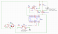
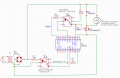
This is what I came up with, forgive first time using EasyEDA, and drawing a circuit. The 27VAC is rectified and sent through 4N25 optocoupler, generating 5V to trigger interrupt on audrino every zero crossing. Through audrino code I count the on-time, measure the duty cycle, and generate PWM out of pin 28 (really 5), this triggers another 4N25 which triggers a mosfet to switch the 31VDC and the constant current driver.

I decided to use two 4n25's because I couldnt connect the common A/C ground to the audrino ground because they were originally separated by an optocoupler, and it didnt seem to like it (started buzzing, any test LED lit up unexpectedly)

This circuit actually works, but I dont know if its doing any damage to the fixture as it's DMX stopped functioning correctly. This could also have happened during testing/messing around.

TrackspotLEDSketch.PNG

Im sure it can be cleaned up and less redundant, but the only issue now is.. is it correct? and right now im getting the 5VDC on the right side of the first optocoupler from the audrino, but it would have to come from the main power source (31VDC), which may negate the whole dual octocoupler thing? Im only using the octos because its been the cleanest signal for zero cross detection, and third, its relying on 3rd party boost converter to go from 31 to 35V, of which I would have to reverse engineer or add to this circuit.
 

MisterBill2

Joined Jan 23, 2018
28,258
The drawing may or not be correct, but it is better and easier to follow than many of the drawings that I have seen. One hint, though, is that where lines cross but don't connect, a half-circle "hopover" will still be clear even after the drawing has been faxed a couple of times. Other than that, quite good for even an experienced drafter!
 
Top