Facebook
 Google
 GitHub
 Linkedin
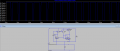
Yes it's called a capacitance multiplier (somewhat of a misnomer), since it does not act just like a large capacitor (which of course, would still draw high peak currents).The input circuit in post #28 is called a capacitance multiplier. It 'multiplies' the capacitance of the 100uf cap, making it seem like the load gets a smoother voltage level.
Im not sure how that would work in the app though because it seems like a fast change in input voltage would cause a fast change in input current
Because the input to the multiplier sees the high transistor collector resistance due to the filter at its base, it suppresses current variation from the V1 source pulses to less than 100mA as the TS requested, with an average of about 58mA.
(Of course all his requirements are still not clear and he hasn't posted in a couple days).
It also isolates the source from the switching regulator current pulses of 168mA .
Below is the .asc file for your amusement.
Attachments
-
2.7 KB Views: 1
Last edited: