 Facebook
 Google
 GitHub
 Linkedin
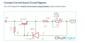
Another circuit we tried and simulate was this one taken from this website - https://circuitdigest.com/electroni...nt-current-generator-circuit-using-transistor
But the power dissipation is too high. About 2Watt...
But the power dissipation is too high. About 2Watt...
Attachments
-
 42.5 KB Views: 12


