Thank you, Danko! ... I'm currently considering winding my own (yeah, I'm that patient ) using the numbers output by this calculator. I'm guessing the amp rating of the coil thus produced will depend on its total impedance, and hence on the wire gauge used to wind it.
Normal cross-section of wire should be 1 square mm for 5A.
It is better use ferrite core with gap.
Anyway, you will need to find maximal allowable current for finished coil.
See on picture below.
Smoothly increase from zero voltage by variac and see on oscilloscope, when sine start distorted.
In this moment notice current I_d on ampermeter . Then maximal current for this coil will 0.9*I_d.
And by the way, Danko. I opened a new thread for me to learn and discuss inductors. So far I've been given very interesting answers. Feel free to join!
We'll start talking about the gap spacers after this thread completes 1,000 posts ... then we could merge it with that other thread you're referring to ...
We'll start talking about the gap spacers after this thread completes 1,000 posts ... then we could merge it with that other thread you're referring to ...
I'm beginning to think we need a new forum, called down the rabbit hole. For things that have a simple, easy, answer but have people piling on to the point they are no longer simple or easy.
I don't know if I've mentioned this. But my winding machine is up and running, and the tensioning system designed around the split capacitor motor being controlled through PWM is behaving absolutely beautifully. The motor maintains perfect tension, does not jitter nor vibrate, and has an extremely low inertia, such that rapid changes in velocity affect the overall tension very little.
Thanks to everyone that helped (or just shared their informed opinions) in this thread. Especially Danko.
As for the caps, I hadn't realized that they can be very easy to find with my local air conditioner suppliers, and in a very wide range of capacitance and voltage values. They're quite inexpensive.
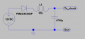
Update. I had to build a second, simpler coil winder to fabricate a few solenoids that I needed. But this time I added the following filter to the circuit feeding power into the controller.
The inductor used is 20 uH @ 3A, 0.02 ohms, toroidal type, MCAP105020023A-200MU.
The 12V power supply is a simple 2A capacity wall wart, but it seems that its filtering is not enough for what I needed. When I switched on the motor controlling the wire tension, and applied a 14KHz PWM to it, spurious resets manifested every once in a while. It wasn't too often so as to make my life impossible, but often enough to be annoying. The circuit had already one 100nF installed for each of its chips, plus a 47uF cap prior to a 12DC to 5DC converter and another one after it. But even with all that things were not perfect until I installed the filter.
From now on, I'm going to install a filter just like this one on every machine I build that involves motors working from the same AC source as the controller's power supply. Hell, I might just add three more 4,700 uF caps in parallel just to be on the safe side of things. But I'm not sure if I've used the proper inductor size nor how to test it, though.
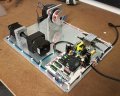
For the curious, here's a couple of pics of my little machine.
And here's a screenshot of the .NET software I wrote to control it.
I used to design the controls and instrumentation for industrial testing machines. Then I did the whole design for a few machines. That was fun. Then I went to work at a start-up, for a lot more money. Sometimes that was not so much fun. Then it went broke, no fun at all. Then I was a contract engineer for a couple different companies. I learned a lot about the different types of managers. Those who can not create instead choose to focus on neatness. I would pity them except that they are overpaid and under-talented and usually not nice people. Oh Well.
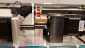
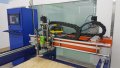
The more complicated machine looks interesting. I see at least 3 axis. What does it do?
It's a two-headed drilling machine for manufacturing precision plywood templates used for the fabrication of automotive electrical harnesses. The machine has a closed-loop current monitoring system enabling to drill up to 8 layers of 1/2" plywood simultaneously.
I use a CNC controller of my own design ... it's completely built using the 8051 architecture, and works with a 10-bit speed resolution, which I've found to be enough for the kind of projects I've been involved with. And the good thing is that the system is address-based for each axis, and so can do simultaneous interpolation of up to 255 axes. Although it is not yet capable of performing routing operations ... but I'm currently working on it
The entire project's firmware is written in assembly, and its software in .NET. I'm using the MCP2221A chip to communicate to the computer through a virtual COM using a USB port.
Thanks, Tony. But that idea is what I call a "passive" tensioner, and what I want is an active one. That is, if the wire sags because the winder stalled a bit, or backtracked (which is something that can happen in my design, because of certain features that I incorporated in it), I need the mechanism controlling the spool to be able to re-wind a little bit, so as to maintain tension.
@cmartinez
To my knowledge a common tension control method (used by wire makers, paper mills, thread & rope makers, etc) is to separate the supply and take-up spools/reels by some distance. Near the middle of that distance, the wire(rope, paper) is deflected (at right angle to the wire movement) by a pulley pressing (or pulling) with a constant force (or nearly constant, as from a spring or weight). A constant tension results in a constant deflection. Measuring the deflection allows tension control via either or both of the supply spool and take-up spool. There are several similar schemes, e.g. wherein the wire is wrapped 180° around a pulley and both supply and take-up reels are on the same side of the pulley (i.e. the wire makes a semicircular loop along the path from the supply to the take-up); in that scheme, applying constant force to the pulley axis results in constant tension of the wire--with no need to measure the deflection/movement (unless the pulley force varies with position) with tension control again applied via supply & take-up reels. If the pulley assy is lightweight, it can quickly change position to maintain tension while the supply & take-up reels are still responding, giving better control.
It's a two-headed drilling machine for manufacturing precision plywood templates used for the fabrication of automotive electrical harnesses. The machine has a closed-loop current monitoring system enabling to drill up to 8 layers of 1/2" plywood simultaneously.
Interesting indeed. I have programmed and created the connection arrangements for machines that check electrical harness installations but I never gave a thought to how the harness assemblies were made. To keep up with the production rate of a car per minute it must take a lot of harness builders, even if they are robots.

 Facebook
 Google
 GitHub
 Linkedin