Controlling wire tension in a coil winder

Danko

Joined Nov 22, 2017
2,199
@cmartinez, pay attention to post #98.
There problem with EMI resolved (at least in simulation) by next pair mosfets M3, M4 which works as freewheel diode and provides continuous current through inductive load.
Much better way is not produce spikes, than suppress them after producing.
 
Last edited:

Reloadron

Joined Jan 15, 2015
7,893
It's official. The 8 hour mark has been shattered, and my circuit has been performing flawlessly without a single glitch. All this because of a single 20¢ component installed in the right place. I couldn't be more pleased.... nighty night, everyone ... :)
Then I believe celebration is in order so grill something. :)

Ron
 

Thread Starter

cmartinez

Joined Jan 17, 2007
8,799
@cmartinez, pay attention to post #98.
There problem with EMI resolved (at least in simulation) by next pair mosfets M3, M4 which works as freewheel diode and provides continuous current through inductive load.
Much better way is not produce spikes, than suppress them after producing.
I did pay attention to that post. But my circuit was already built and assembled, it was much easier to add the TVS. But you're right about it being a better option. I'll integrate your solution into my next circuit, see how it performs.

Here's an odd fact: For safety reasons, I have connected the motor's chassis to my house's ground. The controller I built is being powered by an ordinary wall adapter, and therefore it's "floating" with respect to my house's ground. But if I connect my circuit's ground to the motor's chassis, then my circuit's MCU "glitches" and starts resetting itself uncontrollably. If I leave my circuit "floating" then it works perfectly without a problem. In fact, I left it turned on last night for more than 12 hours straight, and it performed flawlessly.

EMI is a very strange and mysterious thing.
 

Thread Starter

cmartinez

Joined Jan 17, 2007
8,799
Then I believe celebration is in order so grill something. :)

Ron
I already did! ... last night I grilled a few racks of rib-eye ribs, and I'm afraid to say that they came out among the best I've ever done :) ... but sorry, no pics this time. Next time I'll take some for you to admire and drool over, promise :p:D
 

Thread Starter

cmartinez

Joined Jan 17, 2007
8,799
And by the way, Danko. I tried to integrate the new motor model that you did in post #103 into the circuit that you previously did, and I get an error from LTspice saying "K1: coupling to non-existent inductor L4"

upload_2018-6-3_12-35-58.png

I suppose that it has something to do with the directive that you added to the motor's model. But I'm afraid I don't quite understand it and don't know how to correct it.
 

Attachments

Danko

Joined Nov 22, 2017
2,199
K is coupling coefficient. Windings of motor are placed on common ferromagnetic core and coupled against each other by magnetic flux. Exactly as in transformer.
0.9 mean that 90% of magnetic flux is common for windings, but 10% is leakage flux, which does not follow the particularly intended path in a magnetic circuit.
K1, K2... is the same as R1, R2... or C1, C2...
 

Thread Starter

cmartinez

Joined Jan 17, 2007
8,799
K is coupling coefficient. Windings of motor are placed on common ferromagnetic core and coupled against each other by magnetic flux. Exactly as in transformer.
0.9 mean that 90% of magnetic flux is common for windings, but 10% is leakage flux, which does not follow the particularly intended path in a magnetic circuit.
K1, K2... is the same as R1, R2... or C1, C2...
Which means that you're assigning a 90% efficiency to the windings' magnetic coupling, is that right?
 

Danko

Joined Nov 22, 2017
2,199
Which means that you're assigning a 90% efficiency to the windings' magnetic coupling, is that right?
Not exactly. It is not about efficiency, simple 10% of magnetic flux works as pure inductance and do not consumes any energy, only slightly shifts phase of current in mains.
 

Thread Starter

cmartinez

Joined Jan 17, 2007
8,799
Thanks for the explanation, Danko. I think I'm beginning to understand. Would you mind answering a few questions for me? I'd very much like to learn what each part of the circuit does, and why you put it there.

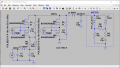
upload_2018-6-3_21-26-5.png

It is clear to me that M1 and M2 are in charge of allowing current to reach the motor. Are L3 and and C5 performing the function of an LC filter to prevent some sort of resonance due to the switching?

Also, R1 and C3 and R3 and C4 are RC filters that are there to absorb the inductive "spikes" produced by the Fet's switching, is that right?

Now, I can see that M3 and M4 are being switched on when M1 and M2 are switched off. That tells me that they're in charge of sending the motor's back EMF current back into the motor's coils, where it will be dissipated as heat, thereby inhibiting the production of EMI, is that right?

Another very important question. Your circuit is designed to run at 20 KHz, would it work just the same if I were to run it at 14 KHz instead, or would some of the values of the capacitors and inductors need to be adjusted?

I assume that changing the duty cycle (your circuit is currently configured to run at 50% PWM, as I can see) won't affect its performance, right?

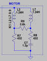
And finally, I think I more or less understand what L3 and C5 are doing. But would you mind explaining to me this part of the circuit?:

upload_2018-6-3_21-27-9.png

Many, many thanks for all your time.
 

Danko

Joined Nov 22, 2017
2,199
Thanks for the explanation, Danko. I think I'm beginning to understand. Would you mind answering a few questions for me? I'd very much like to learn what each part of the circuit does, and why you put it there.
Circuit works good (in simulation) in range 10…20KHz and PWM 0…100%.
Components:
R_line - used for simulation only.
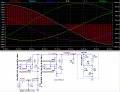
C1, L1, C2 – LC filter, converts 10…20KHz rectangular current pulses (1-st source of EMI) to smooth 60 Hz sine current.
R1, C3 and R2, C4 – RC filters (snubbers), suppress high voltage spikes (2-nd source of EMI) produced in dead time.
L2, C5 – LC filter, converts 10…20KHz rectangular voltage pulses (3-rd source of EMI) to smooth 60 Hz sine voltage.
M1, M2 – bipolar switch, modulator.
M3, M4 – bipolar switch, provides continuity of load current.
Driver for switches M1, M2 and M3, M4 should have dead time 400ns for period (200ns between adjacent pulses PWM1 and PWM2).
L1, L2 – chokes SS26V-070510, 51mH, 700mA
http://uk.farnell.com/kemet/ss26v-070510/common-mode-filter-51000uh-thd/dp/2364331?pf=111468890&inductance=51mh&anyFilterApplied=true&ddkey=http:en-GB/Element14_United_Kingdom/c/passive-components/filters/common-mode-chokes-filters
 
Last edited:

Thread Starter

cmartinez

Joined Jan 17, 2007
8,799
Circuit works good (in simulation) in range 10…20KHz and PWM 0…100%.
Components:
R_line - used for simulation only.

Circuit works good (in simulation) in range 10…20KHz and PWM 0…100%.
Components:
R_line - used for simulation only.
C1, L1, C2 – LC filter, converts 10…20KHz rectangular current pulses (1-st source of EMI) to smooth 60 Hz sine current.
R1, C3 and R2, C4 – RC filters (snubbers), suppress high voltage spikes (2-nd source of EMI) produced in dead time.
L2, C5 – LC filter, converts 10…20KHz rectangular voltage pulses (3-rd source of EMI) to smooth 60 Hz sine voltage.
M1, M2 – bipolar switch, modulator.
M3, M4 – bipolar switch, provides continuity of load current.
Driver for switches M1, M2 and M3, M4 should have dead time 400ns for period (200ns between adjacent pulses PWM1 and PWM2).
L1, L2 – chokes SS26V-070510, 51mH, 700mA
http://uk.farnell.com/kemet/ss26v-070510/common-mode-filter-51000uh-thd/dp/2364331?pf=111468890&inductance=51mh&anyFilterApplied=true&ddkey=http:en-GB/Element14_United_Kingdom/c/passive-components/filters/common-mode-chokes-filters
This time you have outdone yourself, my friend. Many, many thanks! :)
 

Thread Starter

cmartinez

Joined Jan 17, 2007
8,799
Circuit works good (in simulation) in range 10…20KHz and PWM 0…100%.
Components:
R_line - used for simulation only.

Circuit works good (in simulation) in range 10…20KHz and PWM 0…100%.
Components:
R_line - used for simulation only.
C1, L1, C2 – LC filter, converts 10…20KHz rectangular current pulses (1-st source of EMI) to smooth 60 Hz sine current.
R1, C3 and R2, C4 – RC filters (snubbers), suppress high voltage spikes (2-nd source of EMI) produced in dead time.
L2, C5 – LC filter, converts 10…20KHz rectangular voltage pulses (3-rd source of EMI) to smooth 60 Hz sine voltage.
M1, M2 – bipolar switch, modulator.
M3, M4 – bipolar switch, provides continuity of load current.
Driver for switches M1, M2 and M3, M4 should have dead time 400ns for period (200ns between adjacent pulses PWM1 and PWM2).
L1, L2 – chokes SS26V-070510, 51mH, 700mA
http://uk.farnell.com/kemet/ss26v-070510/common-mode-filter-51000uh-thd/dp/2364331?pf=111468890&inductance=51mh&anyFilterApplied=true&ddkey=http:en-GB/Element14_United_Kingdom/c/passive-components/filters/common-mode-chokes-filters
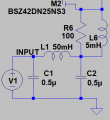
And what are R6 and L6 supposed to be doing?
 

Thread Starter

cmartinez

Joined Jan 17, 2007
8,799
With R6 and L6 circuit can works without dead time between PWM1 and PWM2 pulses, but they distort form of 10...20KHz pulses, R6 dissipates too much energy and some spikes grow up.
And that's why you removed them from the latest circuit? ... I have no problem with generating the 200 ns deadtime between pulses that you're requesting.
 

Danko

Joined Nov 22, 2017
2,199
And that's why you removed them from the latest circuit? ... I have no problem with generating the 200 ns deadtime between pulses that you're requesting.
Yes, it is (about R6, L6 removed). If no problem with dead time, then with farnell chokes you can forget about EMI.
 

Thread Starter

cmartinez

Joined Jan 17, 2007
8,799
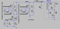
Here is circuit 10...20KHz PWM:
View attachment 153726
One question, Danko. A while ago, I designed a PWM controller for a 90VDC motor that's been behaving quite acceptably ever since. But I'd like to add an EMI filtering similar to the one that you've so generously designed and posted here. What are the underlying equations that determine the values of the components that you've used?

For example, L1, C1 and C2, and then the R1C3 and R2C4 pairs, and finally, L2C5.
 
Top