The response time and stability of any electronic control system will be very critical. The inertia of the tension controlling motor will have a big part in the response time. So you will still need a dancer roll, that uses gravity, to stablize the tension.
AND, there will be that big conflict between production rate, production yield, and production costs.
The response time and stability of any electronic control system will be very critical. The inertia of the tension controlling motor will have a big part in the response time. So you will still need a dancer roll, that uses gravity, to stablize the tension.
AND, there will be that big conflict between production rate, production yield, and production costs.
Yeap ... those are all factors that have been thoroughly considered ... but I still have to build the system and test it. I just want to make sure that this part is completely covered.
Danko, you were right about the motor's temperature rating. The insulation on the wires feel different than ordinary pvc. And after taking a closer look, there's a small print showing that it's rated at 90°C
To clarify things: The coil winder will be controlled by a step motor running at very fine steps (about 1,600 per revolution), it's the stepper that will be doing the winding. A second stepper will guide the wire and form the layers of the coil, whilst this last induction motor will be solely in charge of controlling the tension.
So the plan is to use the induction motor in a permanently stalled way, opposing the step motor performing the winding. The winding's geometry is very asymmetrical, but the step motor's motion profile is controlled in such a way so as to vary its speed in order to compensate for the winding's asymmetry, resulting in a constant speed of the wire as it leaves the spool.
As long as the wire's velocity remains constant, the motor's inertia is unimportant. It is only when the winding procedure starts and ends when a pre-calculated acceleration and deceleration profile of the wire's speed will be performed.
It is also possible to do braking by application of a DC voltage to the winding of most induction motors. And the brke torque is fairly proportional to the current, up to a point. That may allow you to use a much simpler control scheme.
It is also possible to do braking by application of a DC voltage to the winding of most induction motors. And the brke torque is fairly proportional to the current, up to a point. That may allow you to use a much simpler control scheme.
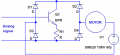
Very interesting, but I'm already applying PWM to the AC voltage, using a couple of Mosfets back-to-back, using a driver powered by an isolated power supply, and switched by an optocoupler... If the technique you're suggesting is better than that at reducing EMI, how could I go around applying DC voltage to such motor without breaking the house? Also, would that scheme produce reverse motion in the motor, or would it just make it resist it?
Dc bias does not tend to produce motion in an induction motor, only resistance to motion, generally proportional to the speed..So no back driving force. Because it is a steady voltage there is no inherent EMI or RFI generated. At one time an analog sensor was used to monitor a dancer roll and adjust the braking current to hold the roll in position. That was very simple. It was not particularly efficient but that did not matter.
DC braking of an induction motor does not need anything close to the AC voltage used to drive it. Thus it does not take as much current, either. So a bit of experimentation with a DC supply will provide a rapid and cheap education. Do you know how much braking torque will actually be required? Also, consider controlling the pay-out wire tension rather than the wire speed. The tension may be a lot easier to control and to monitor.
Not yet, but that's the reason why I'm being so thorough with preparing myself to face this problem when I have the machine up and running. In fact, a dancer roll working on the pay-out wire is still on the table... but I promise you guys I'll keep you posted on whatever happens.
Well, I've set the entire thing up and I must say that it's behaving beautifully. I had custom-made four special spools for this project, and I've already pre-loaded them with magnet wire of gauges #32, #34 and #38 using the same motor that will be controlling the tension when I finally start producing windings. I was able to wind gauge #32 with 100% power to the motor, and also #34. Although maybe I should've eased on the tension a little bit on gauge #34. But it didn't break, fortunately.
Gauge #38 was a different story, as soon as I started the motor, the wire broke. Then I downgraded to 80% PWM, and was able to load a spool to about 10% of its capacity before it broke. Then I lowered the PWM to about 60%, and everything went smoothly until I had about 35% of the spool wound up and I did something clumsy and the wire broke.
What I did was hold the commercial, original plastic spool in which the wire was wound in my left hand, using a small metal rod as an axis, and guided the wire with my right hand as it was being wound into the specially fabricated spools. It was when I did something clumsy with my left hand and braked the spool too quickly as it was spinning that the wire broke. Gauges #32 and #34 behaved much more nobly, allowing for a few mistakes without breaking.
Long ago I discovered that wire strength drops very rapidly as the gauge number increases, and that makes a lot of things a lot more challenging. Another challenge will be the skill level and response times of the operator running the setup, since unless the whole system is completely automated a good part of the production yield will depend on operator skill, and a very fine touch.
One of your design trade-offs will be the compromise between the number of turns and the wire size, given that the bobbin area is the same. For a real challenge, try winding a rectangular coil for an electric guitar pickup. The wire feed speed changes twice in each revolution of the coil.
After much testing, it seems that I've finally tamed the EMI monster ... I did some experimenting here and there, and the MCU stopped resetting itself sporadically when I placed a TVS across the motor's leads.
In retrospective, it makes perfect sense. Even though the back-to-back n-mosfets that I'm using have been protected from over-voltage through the use of another TVS between them, there was nothing stopping the inductive kickback generated by the motor itself when it was being switched off by the PWM signal. So a TVS across its leads absorbs those voltage spikes, and hence suppresses EMI emissions. At least that's my theory.
My device has been applying PWM at 85% duty cycle to the 110VAC split capacitor motor for a couple of hours now, and the MCU has not glitched one bit... As a reference, before installing the TVS, the MCU would reset itself after just three minutes. I'm going to leave this thing on overnight, and see how things are in the morning.
It's official. The 8 hour mark has been shattered, and my circuit has been performing flawlessly without a single glitch. All this because of a single 20¢ component installed in the right place. I couldn't be more pleased.... nighty night, everyone ...

 Facebook
 Google
 GitHub
 Linkedin