Controlling the brightness of LED's with a semiconductor - A simple circuit required please

Sensacell

Joined Jun 19, 2012
3,789
While linear LED dimming does work, it's fraught with many subtle, annoying problems.

These problems can be overcome through careful design, but in the end, the difficulty makes the PWM solution look positively dead simple by comparison.

Bite the bullet and build a PWM circuit- far easier and the results will be much more in line with your expectations.
 

phonic

Joined Sep 29, 2016
37
While linear LED dimming does work, it's fraught with many subtle, annoying problems.

These problems can be overcome through careful design, but in the end, the difficulty makes the PWM solution look positively dead simple by comparison.

Bite the bullet and build a PWM circuit- far easier and the results will be much more in line with your expectations.
Hi Sensacell,

Please support your statements with facts.

The circuit that I posted does not have problems and is precise. It is also simple to build and low cost.

Can we see your proposed circuit using PWM.

phonic
 
Last edited:

Thread Starter

Neville Thannhauser

Joined Dec 3, 2016
27
Hi Phonic and others.

Funny enough I only got round to assembling the circuit yesterday.

Unfortunately I had no success with no led powering. In fact the whole circuit drew no measurable current.

I'm glad you've come back on this as I'm a little out of my comfort zone and could do with some further clarity as your drawing did not display too well on my PC...

Can I use a 2K2 Lin pot instead of the 2K?

Is the R3 (2.7Ω) connecting the source pin to the 0V rail?
Also can a 2.2Ω be substituted?

Can you clarify the value of the R connecting the gate to pin1

If I do not need the second amplifier (pin 5,6,7) does it need to be connected?

Many thanks.
 

GopherT

Joined Nov 23, 2012
8,009
Hi Phonic and others.

Funny enough I only got round to assembling the circuit yesterday.

Unfortunately I had no success with no led powering. In fact the whole circuit drew no measurable current.

I'm glad you've come back on this as I'm a little out of my comfort zone and could do with some further clarity as your drawing did not display too well on my PC...

Can I use a 2K2 Lin pot instead of the 2K?
Yes
Is the R3 (2.7Ω) connecting the source pin to the 0V rail?
Yes
Also can a 2.2Ω be substituted?
Yes
Can you clarify the value of the R connecting the gate to pin1
Value is not critical. It can be omitted on a DIY circuit but 10 to 100 is common - it usually helps reduce RF emissions and keeps the product within FCC compliance.
[/quote]

If I do not need the second amplifier (pin 5,6,7) does it need to be connected?
it should be connected but not the way recommended. Connect the output to (-) input. Connect (+) input to ground.
[/quote]

Also, the design you selected is more complicated and less reliable than a design based on a PWM light control from a 555 timer.

The design you selected (was forced on you) uses a MOSFET in linear mode (not fully on or off). A BJT transistor is better suited for that (actually a bjt darlington). The PWM simply turns the LED on and off at a constant frequency but changes the ratio of on vs off (aka "duty cycle").
 

dannyf

Joined Sep 13, 2015
2,197
Unfortunately I had no success with no led powering. In fact the whole circuit drew no measurable current.
there is so little information there that it made impossible for others to help you diagnose your problems.

not sure which ones you built, but they are all quite simple, especially the bjt / mosfet ones. aside from wiring, it is hard to see how you could have gotten it wrong.
 

dannyf

Joined Sep 13, 2015
2,197
Can I use a 2K2 Lin pot instead of the 2K?
yes.

Is the R3 (2.7Ω) connecting the source pin to the 0V rail?
Also can a 2.2Ω be substituted?
maybe: that resistor sets, together with the pot, the current through the leds. here, with 8 strings of leds, each @ 30ma, you need to have a maximum current of 240ma. the voltage on the pot is 2v max, so you need a resistor of 2 / 240ma = 8 - 10ohm. 4x or 5x of 2.2R would be perfect.

Can you clarify the value of the R connecting the gate to pin1
inmaterial if you are using a mosfet. it can be ignored.
If I do not need the second amplifier (pin 5,6,7) does it need to be connected?
generally no - it depends on the opamp used.
 

Thread Starter

Neville Thannhauser

Joined Dec 3, 2016
27
Thanks for all your help on this.

Now that I have clarity of some on the unclear values in Phonics design I'll continue trying to make it work.

Plan B is the 555 type circuit.
I've found this one: http://www.circuitdiagram.org/555-pwm-led-dimmer.html
I have all the bits for this bar the BD139 transistor. Would it be possible to substitute it with either of these?
2N3904
2N2369
BC549C

Thanks again for your help
 

GopherT

Joined Nov 23, 2012
8,009
Thanks for all your help on this.

Now that I have clarity of some on the unclear values in Phonics design I'll continue trying to make it work.

Plan B is the 555 type circuit.
I've found this one: http://www.circuitdiagram.org/555-pwm-led-dimmer.html
I have all the bits for this bar the BD139 transistor. Would it be possible to substitute it with either of these?
2N3904
2N2369
BC549C

Thanks again for your help
Just use the MOSFET from your current design instead of the BD139.
 

dannyf

Joined Sep 13, 2015
2,197
Would it be possible to substitute it with either of these?
it depends on how many led strings you want. a 555 by itself is typically good for 200ma and can be pushed beyond that. So you can actually attach some of the led strings to the 555 directly, allowing the rest to be driven by a small bjt.
 

phonic

Joined Sep 29, 2016
37
Hi NT,

Happy 2017
Funny enough I only got round to assembling the circuit yesterday.
Well that is a coincidence that I returned to AAC today, and it was only because I had a few spare moments.:)
Unfortunately I had no success with no led powering. In fact the whole circuit drew no measurable current.
Hmm that is a nuisance- still it is better than an explosion.:D

Don't worry; it is quite normal for a new build not to work!
I'm glad you've come back on this as I'm a little out of my comfort zone and could do with some further clarity as your drawing did not display too well on my PC...
Yes, I only knocked the circuit out quickly while I was working on another similar application. And it was my first post on AAC too..

I will do you a nice pretty clear schematic
Can I use a 2K2 Lin pot instead of the 2K?
Yes as GT says
Is the R3 (2.7Ω) connecting the source pin to the 0V rail?
.
Yes, as GT says
Also can a 2.2Ω be substituted?
Yes, as GT says
Can you clarify the value of the R connecting the gate to pin1
The value shown is 220R which means 220 Ohms.

In case you are wondering what the 220 Ohm resistor does, as it may appear to have no function, especially as this is a DC circuit.
The 220R resistor has two functions:
(1) It acts as a gate stopper. MOSFETs have very high frequency capability coupled with massive parasitic capacitance, the capacitance between the gate and the drain being the most troublesome. The net result is that MOSFETs have a tendency to oscillate at between 4Mz and 6Mhz typically. They wont necessarily oscillate all the time just under certain circuit conditions and also at the most inconvenient times, like when the customer comes to see the equipment.:eek:

To act effectively as a gate stopper the 220 Ohm resistor should be mounted directly on the NMOSFET gate terminal, or pretty close (the vacuum tube boys will recognize this resistor which is called a grid stopper with tubes).

(2) The second function of the gate resistor is to isolate the output of the LM358 from the massive capacitance, both actual and virtual, at the gate of the MOSFET. If the LM358 opamps see too bigger capacitance on their outputs they can misbehave.

The value of the gate stopper resistor is not that critiacal and, if the NMOSFET had a PWM drive, the gate stopper would probably be reduced to 10 Ohms to 47 Ohms.
If I do not need the second amplifier (pin 5,6,7) does it need to be connected?
Yes- you must put all unused sections of a chip, both analog and digital, into a defined stable and safe state, or the spare sections will misbehave and, in extreme cases, even destroy themselves and then the whole chip. This is unlikely with an LM358 though, which is a nice friendly operational amplifier.

phonic
 
Last edited:

phonic

Joined Sep 29, 2016
37
Value is not critical. It can be omitted on a DIY circuit but 10 to 100 is common - it usually helps reduce RF emissions and keeps the product within FCC compliance.
Only partly true but certainly not the whole story- see my post.
If I do not need the second amplifier (pin 5,6,7) does it need to be connected?
it should be connected but not the way recommended. Connect the output to (-) input. Connect (+) input to ground.
A spare opamp can be connected either way. It makes no difference.
Also, the design you selected is more complicated and less reliable than a design based on a PWM light control from a 555 timer
This is nonsense. Let us see your rational, including a full circuit, that demonstrates that PWM is more reliable and simpler. If anything PWM is less reliable, for one thing it is more complicated.
(was forced on you)
Please don't talk nonsense- if anything the OP has had PWM forced down his throat. Also please stick to technical matters and leave the ad hominem attacks out.
The design you selected uses a MOSFET in linear mode (not fully on or off).
And what is your point. Are you saying that MOSFETs cannot be used in the linear mode.
A BJT transistor is better suited for that (actually a bjt darlington).
This is meaningless. In what way is a Darlington better suited? In fact, Darlingtons suffer from many problems that a MOSFET overcomes. That is why MOSFETs are ubiquitous and Darlingtons, to a large degree, are yesterday's news.
The PWM simply turns the LED on and off at a constant frequency but changes the ratio of on vs off (aka "duty cycle").
Show you circuit to demonstrate that PWM does anything 'simply'. A liner circuit is simpler by definition. PWM is not necessarily constant frequency. In fact, some of the simpler type are anything but.

As a general point it should be left to the original designer to pass judgement on his circuit and any modifications to avoid confusion and misunderstandings. On the other hand, constructive, informed, accurate and concise comments are always welcome.

There has been a lot of platitudes about PWM but, as yet, there has been no PWM circuit posted, and I cannot see why.

phonic
 
Last edited:

wayneh

Joined Sep 9, 2010
18,181
...I do know about PWM, but the OP asked for a simple approach and a PWM circuit would not only be more complex but it would be more difficult to understand. ...
First of all, I was replying to the TS, who presumably does not yet know PWM. Second, I only glanced at your circuit before and thought the op-amp was an oscillator and that your circuit was PWM. My bad. I see now it's a constant current power supply and should get the job done just fine.

I think it's debatable whether it's simpler than a 555-based PWM solution. In my opinion, the TS is better served by learning the better dimming method of PWM, even if it were slightly more complicated at the start. I feel it's less complicated than linear control, once mastered. Less concerns about efficiency and heat.
 

phonic

Joined Sep 29, 2016
37
Hi wayneh,

Thanks for your reply.
First of all, I was replying to the TS, who presumably does not yet know PWM. Second, I only glanced at your circuit before and thought the op-amp was an oscillator and that your circuit was PWM. My bad. I see now it's a constant current power supply and should get the job done just fine.
I misunderstood you post and that was my bad. :eek:
I think it's debatable whether it's simpler than a 555-based PWM solution. In my opinion, the TS is better served by learning the better dimming method of PWM, even if it were slightly more complicated at the start. I feel it's less complicated than linear control, once mastered. Less concerns about efficiency and heat.
Well put- I could not agree more.

Yes, heat is always a concern but it is a matter of degree. The total power in the circuit is only 0.030A * 12V * 12 strings = 4.32W. So if all of the power of the LED circuit were dissipated by the NMOSFET, the NMOSFET would not complain. Of course, it would be impossible for the NMOSFET to dissipate all the power in the circuit so the NMOSFET would have a really easy time.

Nice to talk to you wayneh.:)

phonic
 
Last edited:

phonic

Joined Sep 29, 2016
37
POST ISSUE 2 of 2017_01_08

HI NT,

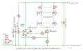
Below is a clearer version of the LED String Brightness Controller.

I have made a few value adjustments here and there and added about three components, but nothing radical.:)

phonic


2017_01_07_AAC_LED_STRING_CONTROLLER_VER!_Iss02.png
​
ERRATA
(1) Fit a 10K resistor from the drain of the NMOSFET to the 12V supply line - thanks Sensacell
​
 
Last edited:

phonic

Joined Sep 29, 2016
37
Hi danny,

I'm sure you are just trying to be helpful, but it is best not to comment on a design if you do not appreciate all the aspects.
maybe: that resistor sets, together with the pot, the current through the leds. here, with 8 strings of leds, each @ 30ma, you need to have a maximum current of 240ma. the voltage on the pot is 2v max, so you need a resistor of 2 / 240ma = 8 - 10ohm. 4x or 5x of 2.2R would be perfect
The resistor most certainly senses the sum of the currents through the 12 LED strings.

With a 10 Ohm resistor that you advise the maximum current through the LED strings would be 2V/10 Ohms = 0.2A but that is short of the OPs stated requirement that the maximum current through each LED is 30mA. With 12 LED strings that gives a maximum current of 0.36A, Not only that, but a 2V overhead would be incurred.

I will not go through the rest of your post, but your advice is not correct. Why you feel it necessary to contradict the original design for no reason is not comprehensible.

phonic
 
Last edited:

wayneh

Joined Sep 9, 2010
18,181
Below is a clearer version of the LED String Brightness Controller
Thanks for drawing this up.

I agree it should work but I do see one issue. A failure (to open) of any LED could cause a catastrophic failure, since the power supply will then attempt to drive the same total current through the remaining strings. They will fail in accelerating fashion. Of course this is true of any arrangement that uses multiple strings on a single constant-current supply.
 

Sensacell

Joined Jun 19, 2012
3,789
I have experimented with the type of linear dimmer circuit shown, I have observed the following:

Problems manifest at low brightness settings.

1) Opamp input offsets and leakage cause the current sink to leak current, the LED's never turn fully off, even with zero input voltage.
Even at micro amp levels, LED's are really good at making light, it's annoying that they don't go 100% dark.
The solution to this problem is to shunt the whole LED stack with a resistor sized to keep the LEDs dark for small leakage currents.

2) When driving parallel stacks, variations in LED Vf cause uneven brightness at low current levels.
Not an issue if you don't run the LEDs at very low brightness levels.
Not much you can do here- increasing the ballast resistor value can help, at the expense of efficiency.
 

phonic

Joined Sep 29, 2016
37
Thanks for drawing this up.

I agree it should work but I do see one issue. A failure (to open) of any LED could cause a catastrophic failure, since the power supply will then attempt to drive the same total current through the remaining strings. They will fail in accelerating fashion. Of course this is true of any arrangement that uses multiple strings on a single constant-current supply.
You can find fault with any circuit by saying, 'what if'.

But your catastrophic scenario is not correct- you have not analyzed the circuit correctly.

If one of the LED strings went open circuit the other LED strings would simply take 1/11 of the total current, at any one current setting rather than 1/12 of the current- hardly catastrophic.

If, on the other, hand all 11 of the LED strings went open circuit, an extreme scenario, the the current through the remaining LED string would be 76mA, assuming that the VF of all the LEDs in the remaining string stayed at 2V. In practice this would not be the case and the LED VF would be considerably higher and as a result the higher current through the remaining string would be much less than 76mA. It is undefined but my guess would be around 45mA. Once again, in either case, hardly catastrophic.

Of course all this depends on the characteristics of the LEDs which is unknown, so I am going by the typical characteristics of medium current LEDs.

spec
 
Last edited:

phonic

Joined Sep 29, 2016
37
I have experimented with the type of linear dimmer circuit shown, I have observed the following:
What does 'this type of circuit' mean. Please focus on the actual circuit posted and don't damn by generalities.
1) Opamp input offsets and leakage cause the current sink to leak current, the LED's never turn fully off, even with zero input voltage.
Even at micro amp levels, LED's are really good at making light, it's annoying that they don't go 100% dark.
The solution to this problem is to shunt the whole LED stack with a resistor sized to keep the LEDs dark for small leakage currents.
You do not quantify the current that will be flowing through the LEDs when the brightness control is at its lowest travel.
How many micro amps minimum do you calculate. 999 uA or 1 uA. It makes a big difference.

But your idea of connecting a parallel resistor to drain off any leakage current is a great idea- thanks for the suggestion.:)
2) When driving parallel stacks, variations in LED Vf cause uneven brightness at low current levels.
Not an issue if you don't run the LEDs at very low brightness levels.
Not much you can do here- increasing the ballast resistor value can help, at the expense of efficiency.
Driving LED stacks in parallel have balance problems.That is true for any circuit.

Variations of brightness are not as apparent as you may think though, because of the eye's logarithmic response to light.

The circuit posted does have balast resistors in each string, which should help.

Incidentally, I did consider a design with 12 constant current generators- one for each string. That would make the current distribution even, but it does not take care of the normally high spread of light output versus current of LEDs, even the best LEDS.

spec
 
Last edited:

dannyf

Joined Sep 13, 2015
2,197
Top