Controlling relay module by using snap switches, no R Pi's or Arduinos

Thread Starter

gwfami

Joined Jan 18, 2018
50
I have a mechanical system I'm building and I want to use snap switches to control the order of operations. The order will be something like this.

1. Run 1 revolution of the electric motor, then stop motor.
2. Activate solenoid.
3. Activate second electric motor for 1 revolution.
4. Begin sequence again.

I see lots of relay modules with 2, 4 or more relays on the board, but they all seem to want to be computer controlled and I have never worked with anything more then 1 relay at a time in simpler circuits with no CPU involved. I've worked with R Pi's and a little with Arduinos, but want to avoid making the device more complex by using them.

So here's my noob question.

Can I drive the relay modules without the computers and if so are there specific ones that I should use? I'm looking specifically at this example, which seems to show it can be done with switches only, but I don't want to just buy something to find out it won't work.

Thanks,

GWFAMI
 

MisterBill2

Joined Jan 23, 2018
19,638
Certainly that functionality can be obtained without a processor module and software. The very difficult portion will be sensing when the motor has turned one revolution. Or are these actually gear-motors that turn more slowly? No mention is made of releasing the solenoid, which will have to happen if the sequence is to repeat. So a more detailed action sequence description will be needed before the scheme can be implemented.
 

MaxHeadRoom

Joined Jul 18, 2013
28,856
1. Run 1 revolution of the electric motor, then stop motor.
2. Activate solenoid.
3. Activate second electric motor for 1 revolution.
4. Begin sequence again.
A simple cam on the motor shaft could be used for the 1 rev/cycle.
Is there any time delay required between operations?
Also the solenoid release question! When!
Unless it is an activate and release?
 

crutschow

Joined Mar 14, 2008
34,933
Your requirements are not complete, so it's not possible to suggest a total design solution.

Please post a complete sequence of the operation, including the switch positions for each step of the sequence, how you will detect the motor position, and the approximate time for each operation.
Without that complete information, we would be just guessing at solutions.
 

MisterBill2

Joined Jan 23, 2018
19,638
The specific details that are not mentioned are the length of time that the solenoid is to remain activated.
In addition, it is not at all clear what the TS means by "Snap Switches"? At this point I am guessing that the TS is intending to describe what I would call "limit switches," mechanically operated by motion of the movements of the mechanical portions of the mechanism described. If the TS
As the TS claims to be an "Other type Engineer", certainly the TS should understand the importance of adequately listing design requirements for a design of any kind. So I am guessing that the following sequence is a complete description, where CR= control relay, LS=Limit switch, TD=Time delay relay, M= Motor, and PB= Normally open push button, NC=normally closed contacts of the device referenced, and NO= normally open contacts of the device referenced. I am also making the incorrect simplifying assumption that the motors stop instantly when their power is removed. In the real world there will need to be some allowance for a bit of coasting that will require some adjustment to compensate for. All relay contacts are assumed to be isolated from all other contacts of the same relay. The initial condition is all at rest.
1 PB1NO is closed, sealing in CR1 via CR1-NO#1 . CR1-NO#2 powers M1
2 M1 rotates until LS#1-NC opens, releasing CR#1, LS#1-NO closes, powering TR#1.
3 TR#1-NO#1 closes, operating the solenoid.
4 LS#2-NO closes when solenoid completes the move.
5 TR#1 times completed, TR#1-NO opens, TR#1-NC closes, solenoid is released
6 CR#2 operates through LS#1 NO and TR#1NC and LS#2 NO and CR#1 NC. and LS#4 NC
7 CR#2 powers motor M2 powering motor #2
8 M2 rotates until LS#4 NC opens, stopping M2.

Probably I have missed a step someplace, but the steps indicated represent the actual ladder sequence fairly well.
What I left out is the intermediate listing of all the actual stages of the operation.

So this is to let the TS understand the level of description actually required to implement sequential motions. It certainly can be done with relays and limit switches and it is not one bit more complex than doing it with a processor or a PLC, although A PLC would simplify wiring a bit.
 
Last edited:

Thread Starter

gwfami

Joined Jan 18, 2018
50
The motors are speed controlled (10-20 rpm) geared motor. I did forget to mention that the solenoid is activated then released in #2.

Certainly that functionality can be obtained without a processor module and software. The very difficult portion will be sensing when the motor has turned one revolution. Or are these actually gear-motors that turn more slowly? No mention is made of releasing the solenoid, which will have to happen if the sequence is to repeat. So a more detailed action sequence description will be needed before the scheme can be implemented.
 

Thread Starter

gwfami

Joined Jan 18, 2018
50
Sorry for the delay, have to sleep sometime.

Limit switch is the correct term. I used the term "Other type engineer" as my degrees are in biology, not engineering.

I appreciate the answers.
 

MaxHeadRoom

Joined Jul 18, 2013
28,856
I'd also like to know more about "snap switches", but the silence of the TS does not bode well.
Often these relate to Micro-switches, that have a 'snap' action however slowly they are activated.
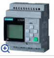
If PLC type control was looked at, a Smart Relay unit would be ample.
 

Thread Starter

gwfami

Joined Jan 18, 2018
50
Ok, you guys talked me into using a PLC type control, my partner in the endeavor wanted all mechanical, but he saw the light. Now, to continue the conversation, should I use an aduino or raspberry pi?
 

BobTPH

Joined Jun 5, 2013
9,346
Ok, you guys talked me into using a PLC type control, my partner in the endeavor wanted all mechanical, but he saw the light. Now, to continue the conversation, should I use an aduino or raspberry pi?
So why are you asking which of two microcontrollers to use when you have decided to use a PLC?
 

Thread Starter

gwfami

Joined Jan 18, 2018
50
So why are you asking which of two microcontrollers to use when you have decided to use a PLC?
Poor communication on my part. We are looking to use either a Pi or Arduino in place of a PLC. Just trying to figure out which of the two would be the best.
 

MisterBill2

Joined Jan 23, 2018
19,638
Neither of those toys is equipped with adequate I/O, nor any durable physical package. If there is any requirement for durability, physical ruggedness, or reliability a little processor board with a bunch of add-on modules connected to each other with flimsy wire, is not the way to go. The control scheme is simple enough to only require two or possibly three relays plus one time delay relay for each solenoid. The benefit is that it would not require a power supply for the logic, nor any programming. It will require understanding every step of the sequence in detail, but you would need that to do it with a processor module as well.
For the best price for a PLC visit "Automation Direct". They also provide free programming software for the products they sell.
 

MaxHeadRoom

Joined Jul 18, 2013
28,856
I have a mechanical system I'm building and I want to use snap switches to control the order of operations. The order will be something like this.

1. Run 1 revolution of the electric motor, then stop motor.
2. Activate solenoid.
3. Activate second electric motor for 1 revolution.
4. Begin sequence again.

I see lots of relay modules with 2, 4 or more relays on the board, but they all seem to want to be computer controlled and I have never worked with anything more then 1 relay at a time in simpler circuits with no CPU involved. I've worked with R Pi's and a little with Arduinos, but want to avoid making the device more complex by using them.
So here's my noob question.
Can I drive the relay modules without the computers and if so are there specific ones that I should use? I'm looking specifically at this example, which seems to show it can be done with switches only, but I don't want to just buy something to find out it won't work.
The link you quoted does not work for me, but the project does appear to be of very simple requirements, it should be quite possible to put together the whole thing using Descrete hard wired components, if necessary.
 
Last edited:
Back in the early 1970s, I had a part time job with my city’s traffic-light department.
Back then, traffic-lights used gearmotor driven cams and microswitches, time delay relays and plain relays to control the lights of even the busiest intersection. (*)
Your project could be duplicated using similar technology, but we live in the 2020s, thus a PLC is the way to go.

* Electromechanical devices continued to be used until the 1990s, when the first ruggedized and very reliable PLCs became available.
 
Top