Controlling motor-driven variacs

Thread Starter

Just Another Sparky

Joined Dec 8, 2019
244
A buddy of mine is giving me a stack of variacs he has no use for. They're paralelled two ways for 0-140V, 100A single phase operation. It happens to be a motor-driven stack.

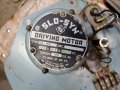
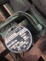
I haven't examined the drive motor yet but rumor on the street is that Powerstat tends to use single phase synchronous motors for this purpose. Working under that assumption, what would my most realistic options be for automating control of this stack for CV & CC operation? I'm thinking along the lines of bulk & taper charging lithium & lead-acid batteries plus the odd supercapacitor array via a rectifier.

Is there anything within the variable frequency/motion control realms that would drive this motor off the shelf? Or would I be better served by sticking to a simpler pulse-jogging control scheme? I'm looking for regulation of about 1% or so depending on how fast this drive motor is geared and how much overshoot will be inherent to it.

I may incorporate a 1.5kVA, 12V transformer to provide higher resolution at low voltages since I'm probably looking at somewhere around 0.5~0.8 volts per turn on these variacs.

Before anyone brings it up; Yes, I am aware that variacs do not provide ground isolation. Grounded systems are my bread & butter. I am a big boy and I know how to handle a solidly grounded 0-200V power supply safely. :p
 

dendad

Joined Feb 20, 2016
4,451
They will probably be split capacitive motors.
The direction can be controlled feeding power to the common and one or the other end of the capacitor connected windings as below.
1633048457909.png
 

Thread Starter

Just Another Sparky

Joined Dec 8, 2019
244
It's gear reduced, but I won't know how much until I get my hands on it this Sunday. Some stacks I've seen turn really fast, others turn at a snail's pace. Depends on what the original owner had in mind I guess.
 

Thread Starter

Just Another Sparky

Joined Dec 8, 2019
244
It appears to be a low speed synchronous stepping motor. Having trouble finding information on it though.

A capacitor and resistor are present in the circuit. Haven't traced it yet due to lack of time but my guess is it's a two phase motor with capacitor shifting and the 250 ohm resistor for braking?

Trouble is I don't know that most stepper drives output 120V. Just for giggles, how hard would it be to build my own stepper drive? If an MCU is needed, perhaps something to the tune of a Parallax Propeller 1?
 

Attachments

Last edited:

MaxHeadRoom

Joined Jul 18, 2013
28,619
It appears to be a low speed synchronous stepping motor. Having trouble finding information on it though.
I have the Slo-Syn info on those motors.
They are designed similar to the AC PSC induction motors, but have permanent magnet poles, and are synchronous, similar to its DC stepper motor cousin.
The have two windings and one has a capacitor/resistor in series with one winding.
They are designed to run at a fixed synchronous speed using the frequency of the mains supply at 72rpm.
 
Last edited:

dendad

Joined Feb 20, 2016
4,451
I would use an Arduino, but you could have 3 comparators. They all have the same ref volts.
One drives a relay to apply power to the motor when the voltage is to high.
Another drives the same relay when the voltage is too low.
But, there is a window that has neither relay operated.
The third drives a second relay that changes the direction of the motor as in post #2.
This third stage is driven by a sense voltage that is between the first and second stage.
Something like this VERY rough circuit (scribbled late at night, so may have errors) but shows the basic idea.

VariacControl.jpg
An Arduino would be easier to adjust in my opinion, but there are folk that have a "religious" belief against them for some reason.
I for one find they are a very handy tool.

The circuit is powered from a small transformer secondary as is the sense AC signal.
 

strantor

Joined Oct 3, 2010
6,782
I would like to get my hands on a stacked variac like that, that I could use to make a 3ph VFD capacitor reforming station. If you get bored with it let me know. My plan was/is just to jog the motor up/down over time. Maybe that doesn't work for you, you might want faster response if trying to make a CC/CV power supply with it. You could always replace that oddball "stepper" with something newer. Steppers and drives are so cheap now.

I have the Slo-Syn info on those motors.
They are designed similar to the AC PSC induction motors, but have permanent magnet poles, and are synchronous, similar to its DC stepper motor cousin.
The have two windings and one has a capacitor/resistor in series with one winding.
They are designed to run at a fixed synchronous speed using the frequency of the mains supply at 72rpm.
Good info. I also encountered one of these in the field recently. I was intrigued by the high voltage with hints of "stepper," enough to take a picture with the intent to do some research on it later, but apparently not intrigued enough to actually follow through. It was used to change the ratio of a variator driven by a fixed speed motor and I was replacing the variator and motor with a new motor and VFD. I was curious though how that was driven.
 

Attachments

MaxHeadRoom

Joined Jul 18, 2013
28,619
. I was intrigued by the high voltage with hints of "stepper," enough to take a picture with the intent to do some research on it later, but apparently not intrigued enough to actually follow through
I came across them in material feeding applications and such, The have excellent 'instant' stop/start characteristics and are quite accurate, RPM wise.
I can post some of the relevant data from the Slo-Syn manual I have on them.
 

Thread Starter

Just Another Sparky

Joined Dec 8, 2019
244
That would be helpful. If they do indeed start and stop more or less instantly then a pulsed control scheme might work.

The bull gear needs to be re-attached to the drive shaft before I can really test that. The cam lobes came loose in the previous owner's posession and the motor was allowed to crash into the end stops, mangling the roll pin securing the gear and introducing quite a bit of slop. In lieu of removing the entire shaft to mill a woodruff keyway into it I'll grind some flats in the shaft and use grub screws to hold it in place. Cup-point 1/4-28 screws on flats with some Loctite 242 should hold it plenty rigid. Else I'll drill and ream for a real taper pin instead of another sh*tty roll pin.
 
Last edited:

Reloadron

Joined Jan 15, 2015
7,501
You may also want to look closely at the existing wiring for any limit switches. I worked years ago with some really large stacks and they all had limit switches. When at full CCW or CW the motor would stop.

Ron
 

Thread Starter

Just Another Sparky

Joined Dec 8, 2019
244
You may also want to look closely at the existing wiring for any limit switches. I worked years ago with some really large stacks and they all had limit switches. When at full CCW or CW the motor would stop.

Ron
The bull gear needs to be re-attached to the drive shaft before I can really test that. The cam lobes came loose in the previous owner's posession and the motor was allowed to crash into the end stops, mangling the roll pin securing the gear and introducing quite a bit of slop.
 
Top