Controlling DC motor when load is ON

Thread Starter

DJ Fahed 1

Joined Sep 1, 2016
13
Hello everybody,

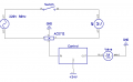
In the circuit attached, I want to turn on the DC motor (valve), which needs 24V as power supply, only and only when the switch is closed, i.e. the AC motor is ON.

The problem is that I don't have access to the AC load, I can only place a current sensor (ASC712) which delivers an image of the current drawn by the load. If there is a current in the AC circuit, the DC motor goes ON, otherwise it stays OFF.

Can anyone please help me at least with idea to how to do that? Thanks.
 

Attachments

cmartinez

Joined Jan 17, 2007
8,252
I'm not sure what you're asking. Are you asking about the what type of control you need to accomplish that? Or do you want to design said control?
Also, may I suggest you take a look at this sensor? There's no need to cut the wire leading to the motor in order to sense the current passing through it.
 

Thread Starter

DJ Fahed 1

Joined Sep 1, 2016
13
I want to design the said control. I want at least the general design of the control box, not necessarily in details.

The ASC712 is the only one I have for the moment, I don't want to purchase others.

Thanks.
 

MaxHeadRoom

Joined Jul 18, 2013
28,681
A couple of things I can see, if you are controlling a 1ph 240v motor why not use the switch to control a contactor (DP BTW) an auxiliary contact on the contactor can pick up the DC motor?
Unless I am missing something, this would be the customary way.
Max.
 

cmartinez

Joined Jan 17, 2007
8,252
Another question. You implied that your valve is motor-controlled. Do you need to reverse the voltage to close it after the other motor (M1) stops running?
 

MaxHeadRoom

Joined Jul 18, 2013
28,681
Or a simple power mosfet to drive the motor direct.
You might want to wire a BEMF diode across the valve, if not reversed.
Max.
 

cmartinez

Joined Jan 17, 2007
8,252
A couple of things I can see, if you are controlling a 1ph 240v motor why not use the switch to control a contactor (DP BTW) an auxiliary contact on the contactor can pick up the DC motor?
Unless I am missing something, this would be the customary way.
Max.
Yup... your suggestion might be the simplest answer ... my personal and humble opinion is that I don't like mechanical contactors, I very much prefer SSRs.
 

MaxHeadRoom

Joined Jul 18, 2013
28,681
Although if the contactor aux was used to turn on a Mosfet, the current would be trivial if not wishing to switch the 24v direct.
Not sure from the Diag whether the AC source is phase pairs or a live and N?
If the latter a single pole power relay with aux would suffice.
Max.
 

Thread Starter

DJ Fahed 1

Joined Sep 1, 2016
13
A couple of things I can see, if you are controlling a 1ph 240v motor why not use the switch to control a contactor (DP BTW) an auxiliary contact on the contactor can pick up the DC motor?
Unless I am missing something, this would be the customary way.
Max.
Actually, the switch is inside the motor. I can't access it, I can only pick up the current drawn by the motor.

The AC source is L & N.
 

Thread Starter

DJ Fahed 1

Joined Sep 1, 2016
13
Another question. You implied that your valve is motor-controlled. Do you need to reverse the voltage to close it after the other motor (M1) stops running?
No, when the circuit closes, the valve closes.

But how to control the SSR using the signal delivered by the sensor?
 

cmartinez

Joined Jan 17, 2007
8,252
See the picture I posted in post #7? Ground would be connected to terminal #4 of the SSR, and your sensor's output would be connected to terminal #3. Whereas your power supply's +24V output would be connected to terminal #1, and terminal #2 to the motor.
 

Thread Starter

DJ Fahed 1

Joined Sep 1, 2016
13
Maybe it would be best if you posted your valve's datasheet, so we can take a look at it.
The valve has only two positions : ON & OFF.
When there is DC voltage across it, it turns fully ON, when there is no DC voltage it closes. It is inside a compressor, and there is no reference number on it.

The ASC712 has a typical sensitivity of 185mV/A, which means that if a minimal current of the motor (load) of 100mA is drawn from the AC source, the sensor will give a signal of 18.5mV. I don't think that's enough the close the SSR?

Other thing, the current drawn by the load is alternative, which mean that it's image is also alternative. How to use that to control the SSR?
 
Top