Controlling current for kanthal wire

Thread Starter

Siddharth Mehrotra

Joined Jul 15, 2019
11
Hello,

I am a newbie to Arduino community!

I have tried out basic projects and wish to learn more :)

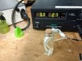
In my next project, I plan to use Kanthal A1 wire wrapped around ceramic wick dipped in scent to produce smell. Here, I want to produce the scent only when the resistance in the stretch sensor goes above certain threshold.

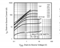
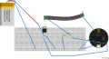
I am using IRLB 8721 mosfet, Adafruit Flora V3, Adafruit Conductive Rubber Cord Stretch Sensor.

The issue I am facing now is MOSFET & battery does heated up very quickly. Also, I think the circuit I have built can be improved.

Suggestions welcome and highly appreciated :)

Code:
  #define RUBBERCORDPIN A11  //This is the pin where the cord is connected tp
   void setup(void) {
     Serial.begin(9600);
     digitalWrite(A7, LOW);
   }
   void loop(void) {
     int value;
     value = analogRead(RUBBERCORDPIN);     //Read value
     Serial.print("Analog reading ");
     if(analogRead(A11) > 250) { //if the analog value of A11 is greater than 250 then
    digitalWrite(A7, HIGH); //write digital pin 7 high
  }
  else {
    digitalWrite(A7, LOW); //
  }
     Serial.println(value);                 //Print value
     delay(1000);
     }
 

Attachments

Hello,

I honestly don't understand well what you're trying to do. According to your schematic, how are you feeding the FLORA? What's the FET load? It seems like you're shorting the FET and the battery. Perhaps if you draw a real schematic with symbol we can have a better insight. I've never been a fan of Fritzing.
 
Last edited:

djsfantasi

Joined Apr 11, 2010
9,156
I agree that Fritzing diagrams are not useful. It is way too easy to make a mistake.

Having said that, it looks as if you are shorting the battery through the FET. Meaning when the gate goes high, a practically unlimited amount of current passes through the FET, creating a lot of heat and potentially destroying the FET.

Secondly, it looks like that “black-tape thingie” is attempted to be driven by a single GPIO pin. If that’s the tape you are heating, I guarantee that it will draw enough current to destroy the GPIO pin, if not the microprocessor.
 

Thread Starter

Siddharth Mehrotra

Joined Jul 15, 2019
11
Thank you so much for the help.

I will try to explain my situation to the best of my knowledge.

I want to use kanthal a1 wire for producing heat. This wire will be wrapped around a ceramic wick dipped inside a scent to produce the smell when the wick is heated (when kanthal wire is wrapped around wick it will cause wick to heatup and producing smell out of scent, see picture of wick in attachment).

About Diagram:
The red color wire is Kanthal Wire. The Kanthal wire I have has Resistance (Ohm/FT @ room temp): 10.55. Using Ohm's Law, if I supply 5V, I need current of 0.47393 amps.

The black tape like thing is Adafruit Conductive Rubber Cord Stretch Sensor.

I am feeding the flora with power from USB.

What I want from my circuit is whenever the resistance in rubber cord increases by 250, turn the MOSFET ON and start heating the wire.

Also, later I plan to control the frequency of the smell produce. Meaning, varying the amount of current Kanthal wire getst so that when required it heats up more and when required less.

I'm sorry for my brevity! I am a high school kid learning electronics.
 

Attachments

Alec_t

Joined Sep 17, 2013
14,280
The Kanthal wire I have has Resistance (Ohm/FT @ room temp): 10.55
What length are you actually using as your heating element?
What are the gate-source voltage and the battery voltage when the circuit is drawing current?
Neither the little PP9 battery nor the breadboard is designed for high current use. 0.5A is pushing your luck.
 

Thread Starter

Siddharth Mehrotra

Joined Jul 15, 2019
11
What length are you actually using as your heating element?
What are the gate-source voltage and the battery voltage when the circuit is drawing current?
Neither the little PP9 battery nor the breadboard is designed for high current use. 0.5A is pushing your luck.
I am using 1 foot of kanthal wire.

Sorry, I don't have multimeter to measure current.

I do understand that breadboard is not a good option here. Can you kindly suggest me what should me what should i do to prevent heating or blowing up the circuit ?
 

Alec_t

Joined Sep 17, 2013
14,280
From the FET datasheet, you need at least ~4.5V to ensure a low Rds(on) and hence to avoid the FET heating significantly. The output voltage from the FLORA may be inadequate. Can you borrow a multimeter to check?
Your little PP3 voltage will drop a lot if you draw a high current from it.
 
Last edited:

djsfantasi

Joined Apr 11, 2010
9,156
One foot of Kanthal wire with a resistance of 10.55Ω and 3.7V across it will draw 350mA. Since the circuit isn’t using a PP3 battery, are you sure that the Ω/ft is 10.55Ω? Kanthal A1 can be as low as 0.324Ω/ft. Do you have a digital caliper and measure the wire diameter. At that lower resistance, you could be drawing 11.4A! ...instead of 350mA.
 
Last edited:

ebeowulf17

Joined Aug 12, 2014
3,307
From the FET datasheet, you need at least ~4.5V to ensure a low Rds(on) and hence to avoid the FET heating significantly. The output voltage from the FLORA may be inadequate. Can you borrow a multimeter to check?
Your little PP9 voltage will drop a lot if you draw a high current from it.
Yes and no - you need over 4.5V for best Rds on, but it still looks ok on the 3.0Vgs line below. 2A of current only yields 0.1Vds (0.2W dissipation,) and even 3A is only 0.2V (0.6W dissipation.) Those amperages are much higher than the TS claims to be running, so I don't think the MOSFET or its gate voltage should be the problem.

upload_2019-7-15_18-51-47.jpeg
I'm leaning towards @djsfantasi 's theory that the heater resistance isn't what it's presumed to be.
 

Attachments

TeeKay6

Joined Apr 20, 2019
573
Yes and no - you need over 4.5V for best Rds on, but it still looks ok on the 3.0Vgs line below. 2A of current only yields 0.1Vds (0.2W dissipation,) and even 3A is only 0.2V (0.6W dissipation.) Those amperages are much higher than the TS claims to be running, so I don't think the MOSFET or its gate voltage should be the problem.

View attachment 181762
I'm leaning towards @djsfantasi 's theory that the heater resistance isn't what it's presumed to be.
@ebeowulf17
Although it does not change your conclusion, bear in mind that the graph you show is "typical", not a guaranteed condition. The MOSFET does have a closely controlled low threshold voltage, compared to more typical 1-4V on general purpose MOSFETs.

Since there is neither temperature control nor current control, (as everyone has observed) operation is extremely dependent on the Kanthal wire resistance.
 

ebeowulf17

Joined Aug 12, 2014
3,307
@ebeowulf17
Although it does not change your conclusion, bear in mind that the graph you show is "typical", not a guaranteed condition. The MOSFET does have a closely controlled low threshold voltage, compared to more typical 1-4V on general purpose MOSFETs.

Since there is neither temperature control nor current control, (as everyone has observed) operation is extremely dependent on the Kanthal wire resistance.
Agreed on all counts!

I didn't worry about tolerances in this case only because the numbers I quoted were for 4-6 times the current that the TS wants to be able to handle. Tolerances can stack up pretty quickly sometimes, but I feel comfortable with a margin that's a factor of four or greater!
 

LesJones

Joined Jan 8, 2017
4,174
You seem to be ignoring post #5 by Dodgydave. I agree with what he says. You have the MOSFET source connected directly to the battery negative and the MOSFET drain connected directly to the battery positive. When the gate of the MOSFET is driven positive the MOSFET will short out the battery.

Les.
 

Thread Starter

Siddharth Mehrotra

Joined Jul 15, 2019
11
One foot of Kanthal wire with a resistance of 10.55Ω and 3.7V across it will draw 350mA. Since the circuit isn’t using a PP3 battery, are you sure that the Ω/ft is 10.55Ω? Kanthal A1 can be as low as 0.324Ω/ft. Do you have a digital caliper and measure the wire diameter. At that lower resistance, you could be drawing 11.4A! ...instead of 350mA.
Thanks for the revert djsfantasi :)

The wire I bought states Kanthal A1 Wrie 22g, 0.2 mm in width, Resistance (Ohm/FT @ room temp): 10.55. I bought from amazon.de, just search Kanthal A1 Wrie 22g (AAC doesn't allow me to post links).

Also, Both the resistors I am using in circuit with conductive stretch sensor are 10K 1%.

I checked my setup without the conductive stretch sensor and saw at this much voltage & current, I am able to get the smell of the scent (see attachment). As a change, I am thinking of following scenario:

Turn ON the heating to a default value when stretch sensor crosses some threshold value. Later based on the varying signals from smart phone change the current supplied to the kanthal wire so that when required it heats up more and when required less.

Can you please help me to recommend what should I do to be able to make this work, considering later I plan to control the frequency & intensity of the smell produce. Meaning, varying the amount of current Kanthal wire gets?

For this I am thinking to use a BLE Nano v2, consisting of a Nordic Semiconductor nRF51822 system on chip. The main role of the BLE Nano is to establish a Bluetooth connection to a smartphone in order to communicate control signals for current. It has an ultra-low power consumption,
integrated Bluetooth Low Energy (LE) capability and it runs at 16MHz. The BLE Nano accepts voltages from 3.3 V to 13 V through the VIN pin and regulates it to 3.3V via an integrated low-dropout regulator.

Also, from what I read from web, MOSFET only requires very little current of the BLE Nano to turn on and delivers a much higher current to the load. In order to save battery life, especially during the high drain phase of the scent release, a capacitor is ideal to be added upstream of the MOSFET.
 

Attachments

Thread Starter

Siddharth Mehrotra

Joined Jul 15, 2019
11
You seem to be ignoring post #5 by Dodgydave. I agree with what he says. You have the MOSFET source connected directly to the battery negative and the MOSFET drain connected directly to the battery positive. When the gate of the MOSFET is driven positive the MOSFET will short out the battery.

Les.
I did that because I saw on web how to control a motor from arduino. I thought the same way I can cause kanthal wire to heat up. However, it didn't worked in my case :/
 

Attachments

LesJones

Joined Jan 8, 2017
4,174
You have not wired it up in a way that is remotely the Arduino diagram in post #15. You need to correct it. You have probably already destroyed the MOSFET.

Les.
 

ebeowulf17

Joined Aug 12, 2014
3,307
About Diagram:
The red color wire is Kanthal Wire.
Your Fet is across the battery, so it will just heat up or blow up!!
You seem to be ignoring post #5 by Dodgydave. I agree with what he says. You have the MOSFET source connected directly to the battery negative and the MOSFET drain connected directly to the battery positive. When the gate of the MOSFET is driven positive the MOSFET will short out the battery.
Dodgy and Les, take another look at the TS's drawing and notice the short length of red wire. If that is the load, and if it's actually around ten ohms, then there's no short circuit scenario (unless I'm misreading the pinouts!)
 

djsfantasi

Joined Apr 11, 2010
9,156
Thanks for the revert djsfantasi :)

The wire I bought states Kanthal A1 Wrie 22g, 0.2 mm in width, Resistance (Ohm/FT @ room temp): 10.55. I bought from amazon.de, just search Kanthal A1 Wrie 22g (AAC doesn't allow me to post links).

Also, Both the resistors I am using in circuit with conductive stretch sensor are 10K 1%.

I checked my setup without the conductive stretch sensor and saw at this much voltage & current, I am able to get the smell of the scent (see attachment). As a change, I am thinking of following scenario:

Turn ON the heating to a default value when stretch sensor crosses some threshold value. Later based on the varying signals from smart phone change the current supplied to the kanthal wire so that when required it heats up more and when required less.

Can you please help me to recommend what should I do to be able to make this work, considering later I plan to control the frequency & intensity of the smell produce. Meaning, varying the amount of current Kanthal wire gets?

For this I am thinking to use a BLE Nano v2, consisting of a Nordic Semiconductor nRF51822 system on chip. The main role of the BLE Nano is to establish a Bluetooth connection to a smartphone in order to communicate control signals for current. It has an ultra-low power consumption,
integrated Bluetooth Low Energy (LE) capability and it runs at 16MHz. The BLE Nano accepts voltages from 3.3 V to 13 V through the VIN pin and regulates it to 3.3V via an integrated low-dropout regulator.

Also, from what I read from web, MOSFET only requires very little current of the BLE Nano to turn on and delivers a much higher current to the load. In order to save battery life, especially during the high drain phase of the scent release, a capacitor is ideal to be added upstream of the MOSFET.

There is an inconsistency in those specs. If it’s 0.2mm in diameter, is not 22g. If it’s 22g, it’s resistance is 1.31Ω!
9206F1A5-8E7A-4231-94B1-7650A555467D.png
If it’s resistance is 1.31Ω, it will draw over 2A at 3.7V.
 

Thread Starter

Siddharth Mehrotra

Joined Jul 15, 2019
11
Hi djsfantasi,

From what I saw on product description, it was written Resistance (Ohm/FT @ room temp): 10.55 (see attachment) & sorry for typo it was 0.02.

If it is drawing over 2A at 3.7 V then my designed circuit is okay ? then everything goes back to starting question to reduce the heat for mosfet and kanthal wire.
 

Attachments

ebeowulf17

Joined Aug 12, 2014
3,307
Hi djsfantasi,

From what I saw on product description, it was written Resistance (Ohm/FT @ room temp): 10.55 (see attachment) & sorry for typo it was 0.02.

If it is drawing over 2A at 3.7 V then my designed circuit is okay ? then everything goes back to starting question to reduce the heat for mosfet and kanthal wire.
Amazon specs are tricky at best, just plain wrong at worst! In your case, it's a single product listing for multiple wire sizes, and the specs should be different for each wire size, but they haven't given you that. Here's one example of info showing resistances (per inch) vs. wire gauge:

Kanthal Wire Gauge (AWG) in Resistance (68°F)
  • 24 Gauge (AWG) = 0.17 Ω / in.
  • 26 Gauge (AWG) = 0.28Ω / in.
  • 28 Gauge (AWG) = 0.44 Ω / in.
  • 30 Gauge (AWG) = 0.70 Ω / in.
  • 32 Gauge (AWG) = 1.09 Ω / in.
  • 34 Gauge (AWG) = 1.76 Ω / in.
You can see that the resistance gets lower with larger wire diameter. This list didn't go up to 22 gauge, but at 24 gauge it's already down to 2.04 ohm for 1 foot. So, your presumed resistance for the heater is probably off by a factor of 5 or more!

It's tricky to do any electronics project without a multi meter, but especially so when you're trying to handle any kind of real power. We might be able to walk you through this particular issue based on specs alone, but I'd STRONGLY urge you to get a meter and start checking your components before using them in the future.

The other lesson here is to be very careful when reading specs, and even more so if you're getting specs from anything other than the product datasheet. Reputable suppliers like digikey, mouser, allied, etc. usually (but not always) get specs right, but Amazon and eBay specs are nearly worthless, and I've heard that Ali Express and other similar sites are even worse. Trust nothing, and verify everything!
 
Top