Controlling an AC load with a MOSFET

MisterBill2

Joined Jan 23, 2018
19,594
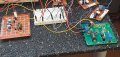
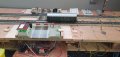
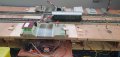
I was thinking about the "CRYDOM" brand of SSRs. But recently I opened one up that that had failed. It was a rude awakening. A TO220 size triac glued to that aluminum back-plate. Not a monolithic encapsulated block.
 

Thread Starter

Holz1

Joined Jan 21, 2020
74
Here's how to connect MOC device with 12VDC input:

View attachment 323733
THANKS!!!!!!
Now a new question arises: How should I interpret the datasheet of the MOC3041:

Source: Motorola
"All devices are guaranteed to trigger at an IF value less than or equal to max IFT.
Therefore, recommended operating IF lies between max IFT (15 mA for MOC3031M & MOC3041M, 10 mA for MOC3032M & MOC3042M, 5 mA for MOC3033M & MOC3043M) and absolute max IF (60 mA)."
ELECTRICAL CHARACTERISTICS:
Forward Voltage(IF = 30 mA)
FV= typ 1.3, MAX 1.5
ZERO CROSSING:
Inhibit Voltage (IF = Rated IFT , MT1–MT2 Voltage above which device will NOT trigger)
VIH= typ. 5V max. 20V

In other factsheets other variables more or less are found.
I read in a fact sheet that the max voltage is 5 V DC and a max input of 10mA: therefore I made the schematic in which I am assuming the numbers I calculated
And there is also the question of the CTR: ( Current Transfer Ratio) and dependency of Voltage and Current input.
Or am I now farfetching?
Regards Henry
 

Attachments

Last edited:

eetech00

Joined Jun 8, 2013
4,060
"All devices are guaranteed to trigger at an IF value less than or equal to max IFT.
Therefore, recommended operating IF lies between max IFT (15 mA for MOC3031M & MOC3041M, 10 mA for MOC3032M & MOC3042M, 5 mA for MOC3033M & MOC3043M) and absolute max IF (60 mA)."
at 15mA the MOC3041 is guaranteed to trigger

ELECTRICAL CHARACTERISTICS:
Forward Voltage(IF = 30 mA)
FV= typ 1.3, MAX 1.5
ZERO CROSSING:
Inhibit Voltage (IF = Rated IFT , MT1–MT2 Voltage above which device will NOT trigger)
VIH= typ. 5V max. 20V
VIH is the voltage across the TRIAC that is required to turn it on and it is a zero-cross parameter.
VIH is typically 5v but could be as much as 20v. If your solenoids operate at 16v, there is a chance that you may obtain a MOC3041 that won't trigger (but still meets the datasheet specification) even if the gate trigger is high enough to turn it on.
 

Thread Starter

Holz1

Joined Jan 21, 2020
74
at 15mA the MOC3041 is guaranteed to trigger


VIH is the voltage across the TRIAC that is required to turn it on and it is a zero-cross parameter.
VIH is typically 5v but could be as much as 20v. If your solenoids operate at 16v, there is a chance that you may obtain a MOC3041 that won't trigger (but still meets the datasheet specification) even if the gate trigger is high enough to turn it on.
Everything is switching and also with 12V R820.

Can I delay the input signal of the MOC3041?
Because the output of MRCS circuit is switching over ground. I tried a timed delayed circuit with NE555, and as I found out, this doesn't work. I tried several possibilities (which I will not present here because all of you will laugh , but at least I try) .

The output pulse of the SN74LS123 is a brief pulse and I donot know if this output pulse can be delayed for a couple of seconds and in this specific circuit the pulse is switched over ground connected to the MOC3041 and TRIAC to the turnouts/semaphores

What I try to get is that the FALLING EDGE of the reset "Q-roofed"1717580507577.png is delayed for 10-15 seconds.
I think this must be done on the PCb it self with additional Rext en Cext whereas the pulseduration remains the same .
 

Attachments

Last edited:

Thread Starter

Holz1

Joined Jan 21, 2020
74
Good morning to you all.
After a week of puzzling with all kinds of IC's(4013, 4051, 4024, 4070-4069), resistors, capacitors on my breadboard, visiting a great variety of websites in order to find the answer to get a pulse delay in the FALLING EDGE output, I found a circuit of Analog Kid.
He posted this circuit on Stack Exchange in Febr. 2022 (https://electronics.stackexchange.c...after-falling-edge-trigger-component-solution).

So, I thought I am putting this circuit in Tiny Cad in order to get it readable for myself and revise the original circuit of the TWIN COIL Driver of ModelRailRoadSystems with the circuit of Analog Kid. ( The original schematic of the TWIN Coil circuit is already posted in this toppic #1 and #11)

My request is to you all and especially to AnalogKid:
1.Is this circuit (which I now post) going to work?
2.And when NOT, what must be done to get it running?
3.Can the delay be altered/changed in more or less delay?

Thanks for your help in advance
(all the IC's which I described above, I used these in time delay-circuits which I found on the web.
The IC CD4060 is not in my possesion: I found a circuit of Dave Johns and Ass. "delayed ONE SHOT pulse generator" of which I think this could also be a solution: http://www.discovercircuits.com/PDF-FILES/DELAYEDONESHOT1.pdf )
And just yet, I found another circuit, which I am going to test; Maybe Analog Kid was referring tothis circuit in his post of Stack Exchange?)
 

Attachments

Last edited:

Thread Starter

Holz1

Joined Jan 21, 2020
74
All of those circuits should work, although the time delays will depend a bit on temperature and supply voltage.
Thanks. How should I alter the time delay of approx 10-20 seconds whereas the pulse WITDH remains 100mS? Please note that the original TWIN coil driver has only been changed at the FALLING edge point and the original OUTPUT circuit will be replaced bij the circuit of AK ( maybe my remark is a little "overdun" but nevertheless, better more info then less info as I have learned)
 

Thread Starter

Holz1

Joined Jan 21, 2020
74
Oké MisterB, I tested the circuit PHOBOSapiens: the 4.7uF didnot the job. I changed it in 100uF and the output pin 4 of the NAND CD4093 is time adjustable between 1 and 30 seconds. So this works.

But now the connection of Q2 (pin 5) of the sn74LS123. Should I connect this pin to the input of the PHOBO or must I use the original layout of the TWIN coil driver ( this is the output of the MOSFET on the PCB ) (I hope you understand what I mean?
 

eetech00

Joined Jun 8, 2013
4,060
Everything is switching and also with 12V R820.

Can I delay the input signal of the MOC3041?
Because the output of MRCS circuit is switching over ground. I tried a timed delayed circuit with NE555, and as I found out, this doesn't work. I tried several possibilities (which I will not present here because all of you will laugh , but at least I try) .

The output pulse of the SN74LS123 is a brief pulse and I donot know if this output pulse can be delayed for a couple of seconds and in this specific circuit the pulse is switched over ground connected to the MOC3041 and TRIAC to the turnouts/semaphores

What I try to get is that the FALLING EDGE of the reset "Q-roofed"View attachment 323882 is delayed for 10-15 seconds.
I think this must be done on the PCb it self with additional Rext en Cext whereas the pulseduration remains the same .
Why is a delay needed?
 

Thread Starter

Holz1

Joined Jan 21, 2020
74
Why is a delay needed?
As explained in my opening post, this Twin Coil driver is switching modelrail Marklin turnouts and twin solenoid Marklin wingsemaphores all working on 16 V AC.

The trigger to switch is an infrared light gate. So when the loc crosses the IR gate, the RISING edge is switching for instance a wingsemaphore. The train needs a certain period of time to pass the IR gate and also needs time to "clear" the track behind it, the FALLING edge should be postponed for 10-20 seconds in order to let down the wing declaring that the track is safe. (This describtion is how I see it in my mind and how I explain it to you!)

An other example with Turnouts. The train passes the IR gate, the turnout is switched and when the loc is through the gate the falling edge triggers and the turnout is switched back while the loc is still on the turnout: The loc derails bcause the front is on 1 side of the track and the end is on the opposing track. I hope you imaging what the situation is!

Regarding the external R (Rext) and C (Cext) for timingpurposes: the Rext and Cext ,as I now know, are for the WITDH of the pulse and not for the DELAY in time on which the pulse is given. With the Rext and Cext is the pulse duration for, let say , 10mS to 100mS. The delay is prolonged to 15 seconds and after that period the original brief pulse (10mS-100mS) is given.
 
Last edited:

eetech00

Joined Jun 8, 2013
4,060
As explained in my opening post, this Twin Coil driver is switching modelrail Marklin turnouts and twin solenoid Marklin wingsemaphores all working on 16 V AC.
OK. I realize this is a model railroad. Keep this in mind while reading my comments below.

The trigger to switch is an infrared light gate. So when the loc crosses the IR gate, the RISING edge is switching for instance a wingsemaphore. The train needs a certain period of time to pass the IR gate and also needs time to "clear" the track behind it, the FALLING edge should be postponed for 10-20 seconds in order to let down the wing declaring that the track is safe. (This describtion is how I see it in my mind and how I explain it to you!)
I know what a semaphore signal is but I don't know what a "wing" semaphore is.
But don't you have a track occupancy detection circuit interlocked with the semaphore?

An other example with Turnouts. The train passes the IR gate, the turnout is switched and when the loc is through the gate the falling edge triggers and the turnout is switched back while the loc is still on the turnout: The loc derails bcause the front is on 1 side of the track and the end is on the opposing track. I hope you imaging what the situation is!
Again, there is usually a track occupancy detection circuit that prevents movement of the turnout until the track circuit is no longer occupied. The track circuit spans the turnout and is longer than the smallest rolling stock.

Regarding the external R (Rext) and C (Cext) for timingpurposes: the Rext and Cext ,as I now know, are for the WITDH of the pulse and not for the DELAY in time on which the pulse is given. With the Rext and Cext is the pulse duration for, let say , 10mS to 100mS. The delay is prolonged to 15 seconds and after that period the original brief pulse (10mS-100mS) is given.
The "pulse width" can be called a "delay" depending on how it is used.
An example is in "the Twin Coil Driver". The output is energized by the input, but the output is de-energized after a DELAY of (10ms-100ms), even if the input is still energized. In the electronics world this functionality is called a "one-shot", or, "monostable", multivibrator.
 

MisterBill2

Joined Jan 23, 2018
19,594
The "wing" semaphore is that flag that changes position either straight sideways or up or down. It is so the engineer can read the signal when the sun is right behind it. A really simple way to avoid unfortunate events.

And I can appreciate that a delay is required in returning the switch. Big trains use a slower mechanism so it is possible no extra delay is required. On model trains it seems that the response time also gets scaled. So an intentional delay must be added.
 

eetech00

Joined Jun 8, 2013
4,060
The "wing" semaphore is that flag that changes position either straight sideways or up or down. It is so the engineer can read the signal when the sun is right behind it. A really simple way to avoid unfortunate events.
I know what a semphore is and how its used. Just never heard them called "wings".
At least not on US railroads in my experience.

And I can appreciate that a delay is required in returning the switch. Big trains use a slower mechanism so it is possible no extra delay is required. On model trains it seems that the response time also gets scaled. So an intentional delay must be added.
Such a delay would be rediculous on a real railroad. The switch and signals (semaphore) would be electrically interlocked (and sometimes mechanically interlocked), so the problem the TS refers to would never happen.
 

MisterBill2

Joined Jan 23, 2018
19,594
Certainly in a real railroad, there is an interlock so that the switch does not shift while any cars or engines are passing over it. They figured that out long ago.
 

Thread Starter

Holz1

Joined Jan 21, 2020
74
Thanks to all of you. I am gratefull that you are also living the dream I have. It still is a dream: a large scale model of a large railway track/layout. I have two "modelrail-enthusast" friends. They have huge scaled railway models. Some tracks are digitalized and some parts and accessories are installed to be as SCENIC ENHANCEMENTS. The wingsingnal is one of those accessories which will be installed on the tracks.

My modelrailway track is smaller: 4 modules of 2.20 meters each and the WIDTH is approx 30cm. I donot have the space to build a large scale platform.
2 x 2 modules (not yet) connected, are hanging above each other against a wall in my house. I still have to connect all the modules and install in each section a Märklin modelrailway crossing with motorized booms, Attiny 85 crossing bell and lights.

My hobby are the electronics and accessories used in the model railroad and solder the parts and components on a pcb andtry to have it functioning. I have NO technical or electronic background nor education so everything must be scrutenized and sift through. In the long end I will understand the technical information you are giving me.
 

Thread Starter

Holz1

Joined Jan 21, 2020
74
Certainly in a real railroad, there is an interlock so that the switch does not shift while any cars or engines are passing over it. They figured that out long ago.
Thanks MrB. I agree to your remark: " Such a delay would be rediculous on a real railroad. "
Therefore I am not a technical engineer with the state railway company.
It would be a great dissaster! :eek:

My request is to you all:
1.Is the circuit (which I now attach) going to work?
(the circuit of PHOBOSapiens I tried and as standalone it works: the ELCO nr 2 is changed into 100uF delay 1 sec-30 sec)
2.And when NOT, what must be done to get it running?

regards
 

Attachments

MisterBill2

Joined Jan 23, 2018
19,594
REally, there is another approach that is probably closer to the way big railroads work. That is an additional sensor that detects any rolling stock, engine or anything else, in the switch area and inhibits any switch motion. It will have the added benefit of preventing a derailment if anything stops on the switch, as well. That could be as simple as a light sensor between the rails that will detect any thing that blocks the light, or, if there is a bit of curve, or even not, detecting anything blocking an IR beam diagonally crossing the track,
Inhibiting is simpler than accurately delaying a movement.
 

Thread Starter

Holz1

Joined Jan 21, 2020
74
THE CIRCUIT IS WORKING!!!! I made the PHOBO circuit on a pcb (didnot worked 1st time, because I forgot to connect the Emitter to ground. Then it took some while to adjust the pots. Then the "piece de la resistance": connecting the input of the delay to the TWIN driver. First I thought the falling edge was connected at pin 5 (R13). Wrong!! It is connected at pin 13 (R12)
I soldererd the lead between pin 13 and R12. It works smashing. The output of the delay is nearly 2 mA. I connected the output of the delay to the solid state relay (on which is also a led present indicating the signal is comming through) and the complete module is working like STAR TREK!!

Thanks guys for your help.
Tomorrow I will try to connect the SSR with TRIAC to the wing semaphores and will let you know if this works also.

Thanks again.
Have a nice evening and tomorrow I show the complete modules on a photo (Hope it works!! otherwise I need your help again):)
 

Thread Starter

Holz1

Joined Jan 21, 2020
74
AS promised, enclosed the photos of the Adjustable delay for the Märklin Semaphore in combination with the Twin Coil driver of MRCS, Solid State relays. As you can notice, I have connected the RISING edge lead directly between pin 5 and R13. I herewith bypass the MOSFETS and can switch the SSR directly. So I think the complete circuit can be smaller for the Märklin Semaphores and turnout which must be switched with AC. (I have do design it first and solder it next
Also attached photos of my Märklin levelcrossing, fully automated and driven by micro motors, and triggered by IR gates.

Thank you guys, I am gratefull for your help!!
Regards
Henry
 

Attachments

Top