Controlling an AC load with a MOSFET

Thread Starter

Holz1

Joined Jan 21, 2020
74
Not quite correct. One AC feed connection is in the wrong corner, where an output is already connected.
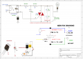
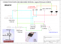
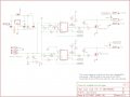
Can you please indicate the wrong position or make a correct drawing: I am now approx 3 days trying to get in running.
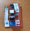
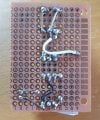
I have removed the mosfets and have the connection made from R15 and R9 as output to the INPUTS of the 2 SSR's .
(see drawing)
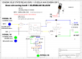
Short info: (maybe not enough but the info previously given, might be sufficient)
The output voltage of the MRCS is below 1 volt and less then 2 mA when switched. I thought to make a new circuit with a BC547 to have a higher output current but the MOC3041 only requires 10mA(max). So, before I will try this I will ask you for a simpler solution
 

Attachments

Thread Starter

Holz1

Joined Jan 21, 2020
74
That circuit has been around since the 1980's. I used that to drive a transformer one time because I did not like the way a triac worked for that. A triac can only be turned off at the zero crossing, while this circuit can be turned off any time. That does bring up its own problems however.

In pseudo theory, you can force the AC wave into a pulsed AC wave and therefore control the power getting to the load and at the same time keep the distortion down. The only problem is there has to be a snubber with it because the inductive kick back can be high and destroy some of the components.

In a regular PWM circuit that drives inductive loads, there is usually a return path built into it so that the kick back power returns to the filter caps and therefore stays lower. With this kind of circuit there is no filter cap so there is no easy way to recover the kickback energy.

The whole idea is that if you short out the DC side of a full wave bridge rectifier you short out the AC side too. That can be used as a switch with a unipolarity switching device like a transistor.
Thanks all, but this grows above my head: I am only a simple hobbyist!
 

MisterBill2

Joined Jan 23, 2018
19,594
GOOD NEWS!! the circuit that was incorrect is now correct I am not sure which one now, because a change has been made by somebody. But now every one of them looks to be correct.
 

Thread Starter

Holz1

Joined Jan 21, 2020
74
GOOD NEWS!! the circuit that was incorrect is now correct I am not sure which one now, because a change has been made by somebody. But now every one of them looks to be correct.
I have made a mistake in the drawing of the SSR: In the 1st drawing PINS 1 and 2 are incorrectly placed. Please see attached drawing and the 2 photo's of the PCB top and bottom side. So the pcb's are by accident correct and are functioning
 

Attachments

Thread Starter

Holz1

Joined Jan 21, 2020
74
Two things about the article.

1. The images on pages 3 and 4 are incorrect. It never is the case that one FET is on while the other is off. They are either both off, in which case the back-to-back diodes block all current; or both on, in which case both diodes are "shorted out" by their respective FETs. This is where the real efficiency gain comes from. The voltage drop across the FET channel could be 10%, or even 1% of the voltage drop across the diode.


2. It skips over the only difficult part of the approach - that little battery symbol between the sources and the gates. This is where there has to be an electrical relationship and physical connection between the DC-powered control board and the AC-powered load. At low voltages this is not a big deal, but at mains voltages it can expose a low-power circuit to lethal voltages.

Don't let my personal bias skew things here - As long as the AC lines to the solenoid are not doing anything else, such as powering the control board, then having the FETs on the control board switch the loads through bridges will work just fine and is simple, reliable, and cheap. You've already paid for the FETs, so let them do the work.

ak
re 1: images on page 3 and 4 (diodes placing) are incorrect:
I attach a new sheet (sheet 4) of the measured contacts of the original pcb board from MRCS. I included in this drawing a picture of the BT136 and the MOSFET IRF520 (as comparison for myself). The measured contacts between the components on the pcb are NOT the contacts of the BT136 but of the IRF520 MOSFET. This could be the observed as the drawing is incorrect.

Image 3: In the left corner I put an image of an example circuit, soI thought I will apply this in my circuit. Butapparently this is NOT GOOD also.
So the remaing question is: what is the right application and circuit which can deliver what I need?
Answers are more than welcome! Thanks in advance
 

Attachments

MisterBill2

Joined Jan 23, 2018
19,594
The new drawing shows a TRIAC, so that no diode bridge is part of the circuit. My original comment was only about one connection to the diode bridge.
 

Thread Starter

Holz1

Joined Jan 21, 2020
74
Thanks all. But I think there is a language barrier and despite the drawings I made (and because of my mistakes in some of the drawings) I donot come further. Maybe I posted to much drawings, maybe I made to much mistakes! What is the modus operandi? From mistakes I learn and when I had all the knowledge of all members of this side, I probably was also an "expert" but I am not!!
In order to get what I like to have, I will try it again by asking:
1.How to connect the TWIN COIL Driver of Modelrailroad control systems (which is operated on 12 Volt DC) to an
AC operated modelrailroad turnout 16V AC?
2.Can someone plse post the schematic how to connect this AC turnout?
3. Is it possible for someone to use the schematic which is posted on #13 by Analog Kid for the connection of the AC 16V turnout?
4. Any help is welcome
Thanks
Henry
 

LowQCab

Joined Nov 6, 2012
4,348
The only problem is that nobody here has a Schematic-Diagram to look at.
And evidently, You don't either.

A complete Schematic is worth more than a thousand words, it's actually required to even start.

Any of the regulars here can solve your problem ............... with a complete Schematic-Diagram.
.
.
.
 

eetech00

Joined Jun 8, 2013
4,061
Thanks all. But I think there is a language barrier and despite the drawings I made (and because of my mistakes in some of the drawings) I donot come further. Maybe I posted to much drawings, maybe I made to much mistakes! What is the modus operandi? From mistakes I learn and when I had all the knowledge of all members of this side, I probably was also an "expert" but I am not!!
In order to get what I like to have, I will try it again by asking:
1.How to connect the TWIN COIL Driver of Modelrailroad control systems (which is operated on 12 Volt DC) to an
AC operated modelrailroad turnout 16V AC?
2.Can someone plse post the schematic how to connect this AC turnout?
3. Is it possible for someone to use the schematic which is posted on #13 by Analog Kid for the connection of the AC 16V turnout?
4. Any help is welcome
Thanks
Henry
Probably the simplest solution is to use a dual, DC input, "solid state relay", or SSR, that supports an AC inductive load. An SSR is similar to an electro-mechanical relay, except there are no moving parts. Some of these devices are very small.
One DC output of the twin coil driver will connect to one input of the SSR and DC common, and the SSR output would connect to one side of the AC solenoid and the 16v AC supply return. Connected in this way, the driver will pulse the SSR, that will in turn pulse the switch machine solenoid coil. The second solenoid would be connected the same way to the second output of the twin coil driver.

Something like this:

1717176021229.png
 
Last edited:

Thread Starter

Holz1

Joined Jan 21, 2020
74
Probably the simplest solution is to use a dual, DC input, "solid state relay", or SSR, that supports an AC inductive load. An SSR is similar to an electro-mechanical relay, except there are no moving parts. Some of these devices are very small.
One DC output of the twin coil driver will connect to one input of the SSR and DC common, and the SSR output would connect to one side of the AC solenoid and the 16v AC supply return. Connected in this way, the driver will pulse the SSR, that will in turn pulse the switch machine solenoid coil. The second solenoid would be connected the same way to the second output of the twin coil driver.

Something like this:

View attachment 323584
Thank you!!! The OUT is switched over DC ground. Am I right?
The only problem is that nobody here has a Schematic-Diagram to look at.
And evidently, You don't either.

A complete Schematic is worth more than a thousand words, it's actually required to even start.

Any of the regulars here can solve your problem ............... with a complete Schematic-Diagram.
.
.
.
I referred to the post of ANALOG KID #13. But to overcome all the searching and clicking at hyperlinks, plse find enclosed the circuit diagram
 

Attachments

Thread Starter

Holz1

Joined Jan 21, 2020
74
Probably the simplest solution is to use a dual, DC input, "solid state relay", or SSR, that supports an AC inductive load. An SSR is similar to an electro-mechanical relay, except there are no moving parts. Some of these devices are very small.
One DC output of the twin coil driver will connect to one input of the SSR and DC common, and the SSR output would connect to one side of the AC solenoid and the 16v AC supply return. Connected in this way, the driver will pulse the SSR, that will in turn pulse the switch machine solenoid coil. The second solenoid would be connected the same way to the second output of the twin coil driver.

Something like this:

View attachment 323584
I am going to try it and will let you know. THANKS for your help.
 

Thread Starter

Holz1

Joined Jan 21, 2020
74
Probably the simplest solution is to use a dual, DC input, "solid state relay", or SSR, that supports an AC inductive load. An SSR is similar to an electro-mechanical relay, except there are no moving parts. Some of these devices are very small.
One DC output of the twin coil driver will connect to one input of the SSR and DC common, and the SSR output would connect to one side of the AC solenoid and the 16v AC supply return. Connected in this way, the driver will pulse the SSR, that will in turn pulse the switch machine solenoid coil. The second solenoid would be connected the same way to the second output of the twin coil driver.

Something like this:

View attachment 323584
"the coin dropped" . In post #13 of AK he referred to:
There are small 1 A and 2 A solid state relays in DIP packages using MOSFETS that should work in this application. OptoMOS

https://www.vishay.com/en/solid-state-relays/
Eetech, with your schematic and the post #13 of AK it is now clear.
 

eetech00

Joined Jun 8, 2013
4,061
"the coin dropped" . In post #13 of AK he referred to:
There are small 1 A and 2 A solid state relays in DIP packages using MOSFETS that should work in this application. OptoMOS

https://www.vishay.com/en/solid-state-relays/
Eetech, with your schematic and the post #13 of AK it is now clear.
Honestly, I did not read AK post #13, but I agree with AK. That is a similar type of device I was thinking to use.
 

eetech00

Joined Jun 8, 2013
4,061
Thank you!!! The OUT is switched over DC ground. Am I right?
Yes. Referring to the drawing I've posted in post #29, the "COIL" terminal should not be connected to anything. The value of the resistors, or if they are even required, depends on the type of SSR being used.

I referred to the post of ANALOG KID #13. But to overcome all the searching and clicking at hyperlinks, plse find enclosed the circuit diagram
Yes. I have already found and reviewed that schematic. The recommended use of an SSR as a DC/AC interface should work.
 

Thread Starter

Holz1

Joined Jan 21, 2020
74
Honestly, I did not read AK post #13, but I agree with AK. That is a similar type of device I was thinking to use.
Thanks!!
I have looking around for this SSR Form A Normally Open, but very difficult to get. Can it be done with a moc3041 and triac BT136? I posted this in #25.
When I takeoff the original MOSFETs from the MRCS board, from what point can I take the output to the MOC3041 INPUT? (I hope you inderstand what I mean) Is it the MOSFET Gate connections R9 and R15 (on the diagram) which could be connected as output to the MOC INPUT?
 

Attachments

eetech00

Joined Jun 8, 2013
4,061
Thanks!!
I have looking around for this SSR Form A Normally Open, but very difficult to get. Can it be done with a moc3041 and triac BT136? I posted this in #25.
Yes. You could use something like that.
But don't use a zero-cross type device for driving an inductive (solenoid) load. Use a "random-phase" type device.
These devices will make the circuit more complex than using an SSR.

When I takeoff the original MOSFETs from the MRCS board, from what point can I take the output to the MOC3041 INPUT? (I hope you inderstand what I mean) Is it the MOSFET Gate connections R9 and R15 (on the diagram) which could be connected as output to the MOC INPUT?
You would connect the internal LED (MOC inputs) to the twin coil driver in the same way as the diagram I've posted in #29.
But each MOC would have to connect to a TRIAC to drive each coil.
 
Last edited:

Thread Starter

Holz1

Joined Jan 21, 2020
74
Yes. You could use something like that.
But don't use a zero-cross type device for driving an inductive (solenoid) load. Use a "random-phase" type device.
These devices will make the circuit more complex than using an SSR.


You would connect the internal LED (MOC inputs) to the twin coil driver in the same way as the diagram I've posted in #29.
But each MOC would have to connect to a TRIAC to drive each coil.
IT WORKS!!!!!!!!! I made a voltage divider from12V DC to 1,5 V DC for the MO3041 but this was to low. Then I put 12 V DC, and it switched like STAR TREK. Then with 5 Volts , the same. 3 volts the same. So I have to find out what the minimum value must be to switch and to be sure that the MOC is not getting to much voltage!. I understand now why AK and Eetech were advising to use the SSR Form A SPST NO and .."These devices will make the circuit more complex than using an SSR" .
These SSR are difficult to get in the Netherlands and when you can get them, it costs a lot of money.
On Aliexpress there are no equivalents to find. (maybe I am not looking good enough !! )

All you guys, THANK THANKS!!!
 

eetech00

Joined Jun 8, 2013
4,061
IT WORKS!!!!!!!!! I made a voltage divider from12V DC to 1,5 V DC for the MO3041 but this was to low. Then I put 12 V DC, and it switched like STAR TREK. Then with 5 Volts , the same. 3 volts the same. So I have to find out what the minimum value must be to switch and to be sure that the MOC is not getting to much voltage!. I understand now why AK and Eetech were advising to use the SSR Form A SPST NO and .."These devices will make the circuit more complex than using an SSR" .
These SSR are difficult to get in the Netherlands and when you can get them, it costs a lot of money.
On Aliexpress there are no equivalents to find. (maybe I am not looking good enough !! )

All you guys, THANK THANKS!!!
Here's how to connect MOC device with 12VDC input:

1717350328527.png
 

MisterBill2

Joined Jan 23, 2018
19,594
You are not alone in seeing that SSR devices are expensive. And that includes right here in the USA, not that far from where some (CRYDOM) are made.
 

MaxHeadRoom

Joined Jul 18, 2013
28,844
You are not alone in seeing that SSR devices are expensive. And that includes right here in the USA, not that far from where some (CRYDOM) are made.
Usually paying for the cost of the enclosure!
I generally put my own together and enclose it in whatever it is controlling.
 
Top