I came across this post:
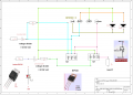
Controlling an AC load with a MOSFET
https://tahmidmc.blogspot.com/2012/11/controlling-ac-load-with-mosfet.html
Can someone explain how this works in simple words or with a circuit diagram.
I don't understand how this works.
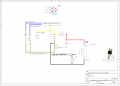
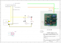
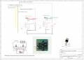
I want to switch a modelrail Märklin M turnout, 2 solenoids 16 Volts AC current, with a TWIN COIL SWITCH machine driver board which is built for DC turnouts or modelrail semaphores twin solenoid wingsignals, 12 Volts DC.
The twin coil driver board is TTL 5 Volts DC containing a SN74LS123 One Shot MVV.
(See : https://www.modelrailroadcontrolsystems.com/twin-coil-switch-machine-driver-board/)
Your help is welcome
greetings
Henry
Controlling an AC load with a MOSFET
https://tahmidmc.blogspot.com/2012/11/controlling-ac-load-with-mosfet.html
Can someone explain how this works in simple words or with a circuit diagram.
I don't understand how this works.
I want to switch a modelrail Märklin M turnout, 2 solenoids 16 Volts AC current, with a TWIN COIL SWITCH machine driver board which is built for DC turnouts or modelrail semaphores twin solenoid wingsignals, 12 Volts DC.
The twin coil driver board is TTL 5 Volts DC containing a SN74LS123 One Shot MVV.
(See : https://www.modelrailroadcontrolsystems.com/twin-coil-switch-machine-driver-board/)
Your help is welcome
greetings
Henry
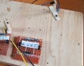
Attachments
-
752.6 KB Views: 34