controlling a 12V dc ball valve

Thread Starter

saintblues

Joined May 15, 2020
27
Hi,

so im trying to control the water flow through a 12V ball valve for a classic car heater using 4-20ma. The water flow of the engines coolant passes into the heater matrix. I would like to control the opening of the valve using a potentiometer; so as i rotate the pot the valve opens gradually and allows more or less water into the heater matrix thus giving me temperature control of the air being blown into the car. the car has a 12/14v battery.

how will this be wired?

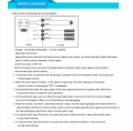
The specs of the valve are below:
Model Number CTF001 Modulating type
Rated Voltage 12V
Working Current <200ma
Output torque MAX 6Nm
Full on off time <30s
Control Mode 4-20ma
working pressure 1mpa
power <5W
medium temperate 0-95 degrees celcius
IP 65 rated

I'm confused as to how this would be wired up and what rated pot i would use. Ive posted pics below of the valve
 

shortbus

Joined Sep 30, 2009
10,045
If using one of those are you going to change the bypass flaps inside the heater housing? Many time heat is controlled by a flap with the coolant constantly flowing. They found that by using the old vacuum controlled valves that they clogged up during the summer months when the heater wasn't used.
 

Thread Starter

saintblues

Joined May 15, 2020
27
If using one of those are you going to change the bypass flaps inside the heater housing? Many time heat is controlled by a flap with the coolant constantly flowing. They found that by using the old vacuum controlled valves that they clogged up during the summer months when the heater wasn't used.
hi, as its a vintage classic car and a simple heater there will be no by-pass flaps. The coolant will just flow constantly from the engine through the valve (when open) then through the matrix and back into the engine and round again.

Are you saying that in summer if i don't use the heater and the ball valve remains shut-closed the valve or the matrix may get clogged with the coolant as it wont be circulating?
 

Reloadron

Joined Jan 15, 2015
7,517
You want a voltage to current source. The idea being you use a potentiometer to adjust for example 0 to 5 volts which proportionally becomes 4 to 20 mA which you send to your valve. You can build or buy the current source. I used 5 volts in my example because 12 volt automotive is not stable and can be 12 to 14.5 volts depending. They make chips which simplify the process. A Google of voltage to current circuits should get you some hits. Why is this under micro-controllers?

Ron
 

Reloadron

Joined Jan 15, 2015
7,517
Are you saying that in summer if i don't use the heater and the ball valve remains shut-closed the valve or the matrix may get clogged with the coolant as it wont be circulating?
Every now and then on my 50 Ford and subsequent cars we would just run the heater every now and then during the summer to keep the core flushed. Heck, sometimes stuck in traffic we would run the heater during a hot summer day just to help remove heat from the engine.

Ron
 

Thread Starter

saintblues

Joined May 15, 2020
27
You want a voltage to current source. The idea being you use a potentiometer to adjust for example 0 to 5 volts which proportionally becomes 4 to 20 mA which you send to your valve. You can build or buy the current source. I used 5 volts in my example because 12 volt automotive is not stable and can be 12 to 14.5 volts depending. They make chips which simplify the process. A Google of voltage to current circuits should get you some hits. Why is this under micro-controllers?

Ron
thank you. so could i use this module https://www.aliexpress.com/item/329...earchweb0_0,searchweb201602_,searchweb201603_

would the following wiring method be correct?
Battery 12 to 14.5V to the potentiometer -----> the potentiometer adjusts the voltage via a rotary knob -------> a voltage between 0-15V then outputs to the voltage to current module-----> 4-20ma supplied out to the valve based on the pots selection.

is the above correct?
 
Last edited:

Thread Starter

saintblues

Joined May 15, 2020
27
Every now and then on my 50 Ford and subsequent cars we would just run the heater every now and then during the summer to keep the core flushed. Heck, sometimes stuck in traffic we would run the heater during a hot summer day just to help remove heat from the engine.

Ron
great idea, thats what ill have to do. ive got an old 1977 mini im doing up
 

Reloadron

Joined Jan 15, 2015
7,517
That's what you want and yeah, a 0 - 15 volt would work. When the voltages increases or decreases as it does on an automotive system there will be some variations but yes, it would work. Yes, that module should work fine.

Ron
 

shortbus

Joined Sep 30, 2009
10,045
Are you saying that in summer if i don't use the heater and the ball valve remains shut-closed the valve or the matrix may get clogged with the coolant as it wont be circulating?
Not the "matrix" as you call it, here we call it the heater core, but the valve it's self. That valve makes that part of the coolant circuit a dead end when it's closed/off. Any rust or other corrosion floating in the coolant will settle out in that dead end. Then when winter comes and you use the heater one of two things happens, either the valve won't open or the accumulated crud that settled out goes through the core and then can clog it up.

Most of these heater valves, in cars that actually use them, are a "by pass" type. Like the capital letter H. With the valve in the horizontal part of the H. When the valve is closed(winter time) the coolant all goes through the heater core. In the summer the valve is open, and since it is less restrictive than the core, most of the coolant flows through the valve, and no corrosion byproducts settle out.

Does the car have a valve in it now? If not I'm betting there is a flapper that keeps the heat out of the air stream when the heater control is shifted from heat to vent. I never saw even an old car(in the USA) that didn't use one in it. And over my years of working on old cars I've changed a lot of heater cores, so had the heaters apart.
 

Thread Starter

saintblues

Joined May 15, 2020
27
That's what you want and yeah, a 0 - 15 volt would work. When the voltages increases or decreases as it does on an automotive system there will be some variations but yes, it would work. Yes, that module should work fine.

Ron
Great, I now however have another dilemma because shortbus above has convinced me to throw in a bypass valve so that the coolant doesnt just stop at the deadend once the valve is closed. I should keep the coolant/water cycling.

Im thinking of adding an additional open/close type valve to run as the bypass valve once the modulating valve is closed. So when the modulating valve is fully closed the bypass valve would automatically open and vice versa when the modulating valve opens even slightly the bypass valve would close.

Im trying to figure out how i would automate this as i dont want so many different switches on the dashboard.

Is it possible to somehow send out a trigger signal to close the bypass valve whenever the pot is rotated to open the modulating valve?
 

Thread Starter

saintblues

Joined May 15, 2020
27
Not the "matrix" as you call it, here we call it the heater core, but the valve it's self. That valve makes that part of the coolant circuit a dead end when it's closed/off. Any rust or other corrosion floating in the coolant will settle out in that dead end. Then when winter comes and you use the heater one of two things happens, either the valve won't open or the accumulated crud that settled out goes through the core and then can clog it up.

Most of these heater valves, in cars that actually use them, are a "by pass" type. Like the capital letter H. With the valve in the horizontal part of the H. When the valve is closed(winter time) the coolant all goes through the heater core. In the summer the valve is open, and since it is less restrictive than the core, most of the coolant flows through the valve, and no corrosion byproducts settle out.

Does the car have a valve in it now? If not I'm betting there is a flapper that keeps the heat out of the air stream when the heater control is shifted from heat to vent. I never saw even an old car(in the USA) that didn't use one in it. And over my years of working on old cars I've changed a lot of heater cores, so had the heaters apart.
I removed the heater as it was an old 1960 heater which didn't provide enough airflow and made too much noise. The water outlets on the engine are currently blanked off. I'm thinking of purchasing a 6 port heater core with fans from Ali Express.

The existing heaters air temperature was controlled by pulling a manual cable to open or close a manual valve on the engine to allow water to circulate through the core. see the pic below. Yes i think your right it has a flapper on it. again see the pic im sure ull recognise the old thing.

Looks like uve convinced me to add a bypass valve. As the engine is modified id like for the water/coolant to continue cycling through rather then being stuck at a dead end. Thinking of maybe another ball valve or solenoid valve.

Im trying to figure out how i would automate this as i dont want so many different switches on the dashboard.

Is it possible to somehow send out a trigger signal to close the bypass valve whenever the pot is rotated to open the modulating valve? perhaps using some sort of trigger module?
 
Last edited:

Thread Starter

saintblues

Joined May 15, 2020
27
20200517_221455_HDR.jpg
currently sealed of with a blank plate. old pull cable type manual water valve


20200517_221520_HDR.jpg
Existing old heater


20200517_221920_HDR.jpg
Flap which moves based on the slider knob on the front of the heater (assume this is what you were talking about?)
 
Last edited:

Reloadron

Joined Jan 15, 2015
7,517
I wouldn't overly worry too much about a bypass. During the summers just open the heater core valve every now and then. However do whatever works best for you. Also in your first image I see what looks like a 90 degree steel elbow, if possible I would replace it with brass.

Ron
 

Thread Starter

saintblues

Joined May 15, 2020
27
I wouldn't overly worry too much about a bypass. During the summers just open the heater core valve every now and then. However do whatever works best for you. Also in your first image I see what looks like a 90 degree steel elbow, if possible I would replace it with brass.

Ron
How difficult would it be to automate a bypass valve? if it is too difficult/expensive I may consider scrapping the idea

Also, can you explain please what the 4-20ma output wire from the modulating valve will connect to? do i simply just leave that disconnected?
 

Reloadron

Joined Jan 15, 2015
7,517
How difficult would it be to automate a bypass valve? if it is too difficult/expensive I may consider scrapping the idea

Also, can you explain please what the 4-20ma output wire from the modulating valve will connect to? do i simply just leave that disconnected?
Automating a bypass valve is hardly worth the effort, just my opinion. A manual bypass is simple and as I mentioned I likely wouldn't bother. Over all the cars during my younger years I only had one, a 63 Ford, where the heater core failed due to blockage. Believe me there were a hell of a lot of cars and trucks. You are only going to use it likely twice a year.

The 4-20 mA out you would not use. The 4-20 mA loop (current loop) is a standard in process control. Lets say I wanted an indication of my valve position. So 4 mA is closed (0%) and 20 mA is open (100%). If I place a resistor across that output of say 500 Ohms there will be a voltage drop proportional to current flow of 2 to 10 volts. So I scale that where 2 volts = 0% and 10 volts =100%. That being just one example. In an automated system I may use it for feedback in a control system. The list gets long. :)

Ron
 

Thread Starter

saintblues

Joined May 15, 2020
27
Automating a bypass valve is hardly worth the effort, just my opinion. A manual bypass is simple and as I mentioned I likely wouldn't bother. Over all the cars during my younger years I only had one, a 63 Ford, where the heater core failed due to blockage. Believe me there were a hell of a lot of cars and trucks. You are only going to use it likely twice a year.

The 4-20 mA out you would not use. The 4-20 mA loop (current loop) is a standard in process control. Lets say I wanted an indication of my valve position. So 4 mA is closed (0%) and 20 mA is open (100%). If I place a resistor across that output of say 500 Ohms there will be a voltage drop proportional to current flow of 2 to 10 volts. So I scale that where 2 volts = 0% and 10 volts =100%. That being just one example. In an automated system I may use it for feedback in a control system. The list gets long. :)

Ron
Completely understand that it may be a waste of time and effort.. In saying this though is there any simple way of automating a bypass valve? for example is there such thing as a 1-15V relay? so that when the pot sends out 1-15V for the modulating valve i could wire the same signal into a relay module which would then send out a full 12V to the bypass valve indicating it to close entirely. Only when the pot is then rotated back to 0V the relay module would lose voltage entirely indicating the bypass valve to open again.

ideas?
 
Top