
 Facebook
 Google
 GitHub
 Linkedin
Hi,
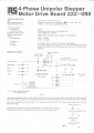
I'm doing a small upgrade to the driving logic of a system involving a stepper motors. The drive board is RS-Electronics 332-098 which specsheet is attached. It should work with 12V external control logic.
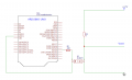
I did my the new logic of the board with Arduino, but now I'm struggling to connect the 5V Arduino to 12V drive board. I tried a simple board with external 12V power supply and an optocoupler but it did not work as I planned (it did not work at all).
According to my tests:
1) The stepper motor and the control board is working as I can drive it with the old controller
2) The optocoupler is working as I can blink a led with it
So it seems that I have just screwed the circuit design. Which kind of (pull-up?) resistor should I use in the drive side of the board?
My optocoupler should withstand 50mA current, which is same than the driving current of the board. Is this too close match?
Circuit:
Drive board:
I'm doing a small upgrade to the driving logic of a system involving a stepper motors. The drive board is RS-Electronics 332-098 which specsheet is attached. It should work with 12V external control logic.
I did my the new logic of the board with Arduino, but now I'm struggling to connect the 5V Arduino to 12V drive board. I tried a simple board with external 12V power supply and an optocoupler but it did not work as I planned (it did not work at all).
According to my tests:
1) The stepper motor and the control board is working as I can drive it with the old controller
2) The optocoupler is working as I can blink a led with it
So it seems that I have just screwed the circuit design. Which kind of (pull-up?) resistor should I use in the drive side of the board?
My optocoupler should withstand 50mA current, which is same than the driving current of the board. Is this too close match?
Circuit:
Drive board:





