
 Facebook
 Google
 GitHub
 Linkedin
Hello there,
I am building a 2-bit parallel load register that is taking inputs from a 4-to-2 binary encoder's outputs and I can't figure out how to control the clock.
The register is part of a bigger circuit that takes in an interrupt and holds it for a predetermined amount of time. Once the time period is over, the register is cleared and is ready for another interrupt. To do this, I am suppose to use an encoder and a register.
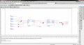
Could someone explain how to control the clock on a register? I know that you can use the status of the register to do so, but I don't know how to implement it into the circuit. I've attached a couple screenshots of what I have done. One is the register and the other is the project as a whole.
Also, in case what I said didn't make any sense, I've added a description of what I am suppose to do.
Any help is appreciated!
Thanks in advance.
I am building a 2-bit parallel load register that is taking inputs from a 4-to-2 binary encoder's outputs and I can't figure out how to control the clock.
The register is part of a bigger circuit that takes in an interrupt and holds it for a predetermined amount of time. Once the time period is over, the register is cleared and is ready for another interrupt. To do this, I am suppose to use an encoder and a register.
Could someone explain how to control the clock on a register? I know that you can use the status of the register to do so, but I don't know how to implement it into the circuit. I've attached a couple screenshots of what I have done. One is the register and the other is the project as a whole.
Also, in case what I said didn't make any sense, I've added a description of what I am suppose to do.
Any help is appreciated!
Thanks in advance.
Attachments
-
 111.7 KB Views: 31
 -
 112.7 KB Views: 26
 -
22.5 KB Views: 16
Last edited:






