Control TFT Backlight.

Status
Not open for further replies.

ericgibbs

Joined Jan 29, 2010
21,552
hi Pepe,
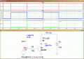
This image shows one option. [the 68R is a Test load ONLY]
There are two points to note:
1. The inversion of the PWM pulse, that should not be a programming problem.
2. The Vled drop of the TFT back light, if its a White LED, the Vfwd could be approx 3.2V, so using a 3.3V supply could be a problem.
Measure the Vled fwd voltage.
E

EDIT:
Some TFT modules expect the Light pin to be connected to 0V, others to +Vcc, which is yours.?
 

Attachments

Last edited:

Thread Starter

Pepe333

Joined Feb 12, 2018
86
hi Pepe,
This image shows one option. [the 68R is a Test load ONLY]
There are two points to note:
1. The inversion of the PWM pulse, that should not be a programming problem.
2. The Vled drop of the TFT back light, if its a White LED, the Vfwd could be approx 3.2V, so using a 3.3V supply could be a problem.
Measure the Vled fwd voltage.
E

EDIT:
Some TFT modules expect the Light pin to be connected to 0V, others to +Vcc, which is yours.?
Thank You!
Mine is LED Pin to Vcc. I tested with a pot and works properly. What I really need is maintain the 0-3.3V on the amplifier output.
I'll test your circuit. Thanks again! :)
 

ericgibbs

Joined Jan 29, 2010
21,552
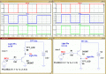
hi P,
Remember the Back LED's are current driven and will require a low value current limiting resistor.
The resistor value is chosen so that the safe operating LED current is not exceeded.
E
Updated Images:
 

Attachments

ericgibbs

Joined Jan 29, 2010
21,552
hi,
I have doubled checked my LTSpice and shows 0.7V not 1V.

Measure the LED current and Voltage in an actual TFT module, we will take it from there, see what we can do to improve it.
Let me know those values.
E
 

philba

Joined Aug 17, 2017
959
Oh, man!
Thank you very much for ypour explanation... it was very clear... maybe you forgot some important points:
1.1 breath.
2.0 plug the soldering iron
3.1 throw a fart

...but the question you didnt answer is: "How to amplify the current, of an output, from 0 to 3..3V from a GPIO giving a 3.3V max.
After your perfect explanation, can you explain how to achieve that?, maybe with a drawing?
You are getting help on the driver transistor so I don't need to add anything there. But the reason I wanted you to make the change is, as I've said several times, with 3.3V on the Vcc pin you are running the board below it's intended operating voltage because of the VReg dropout. In your sims you are using 3.3V but, without the change, it's probably something less than 3.1V. The actual value depends on the Vreg's voltage drop.
 

ebeowulf17

Joined Aug 12, 2014
3,307
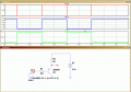
If the GPIO is 3.3V your circuit works properly, but when GPIO is 0v dont works. Look the draw.

View attachment 145823
If you're driving the backlight directly with this circuit, which is what I thought I understood from previous posts, then the voltage across the transistor doesn't matter. What matters is current through the load. I'm not familiar with your simulation program, but it should have a way to put a current measurement inline (in series) with the load.

When the GPIO signal is 0V, you should see maximum current through the load - if you're not happy with the amount of current through the load, you can adjust the resistor value accordingly.

When the GPIO signal is high (why are you using 2.5V instead of 3.3V for high output anyway?) you should see zero current through the load.

The only reason voltage across the transistor (Vce) would be a factor is if the forward voltage of the backlight LED (Vf) is high enough that Vce + Vf is greater than your 3.3V supply.

If Vce really does turn out to be a limiting factor, you could use a logic level MOSFET instead of the BJT.
 
Status
Not open for further replies.
Top