 Facebook
 Google
 GitHub
 Linkedin
Hello, I'm a complete newbie in circuits and have tried to figure it out with chatgpt (yeah, feel free to roast me!).
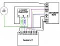
I'm trying to control a DIA42B20W (BLDC motor with in-built driver) with a Raspberry Pi. Please see the diagram on how I plan to wire it all up. I have added a N-MOSFET into my circuit so that I can control the application of the 24V. The reason for this choice is two-fold:
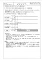
1)The warning below listed in the manual (See photo)
"Prohibition of plugging and unpluggin while Power is ON
Unplugging and inserting the connector in the power ON state may cause breakage, so please do not do it absolutely"
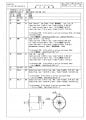
2) To control the timing for the start up so that it matches recommendation in the manual (see diagram in Photo).
Does the circuit make sense? I'm afraid I already fried one motor when I messing about in my first attempt, but I have ordered two more.
Full manual for the BLDC is here:
https://mm.digikey.com/Volume0/opasdata/d220001/medias/docus/2519/DIA42B20W32A_Spec.pdf
I'm trying to control a DIA42B20W (BLDC motor with in-built driver) with a Raspberry Pi. Please see the diagram on how I plan to wire it all up. I have added a N-MOSFET into my circuit so that I can control the application of the 24V. The reason for this choice is two-fold:
1)The warning below listed in the manual (See photo)
"Prohibition of plugging and unpluggin while Power is ON
Unplugging and inserting the connector in the power ON state may cause breakage, so please do not do it absolutely"
2) To control the timing for the start up so that it matches recommendation in the manual (see diagram in Photo).
Does the circuit make sense? I'm afraid I already fried one motor when I messing about in my first attempt, but I have ordered two more.
Full manual for the BLDC is here:
https://mm.digikey.com/Volume0/opasdata/d220001/medias/docus/2519/DIA42B20W32A_Spec.pdf
Attachments
-
 72.4 KB Views: 16
 -
 93.1 KB Views: 17
 -
 113.5 KB Views: 13
 -
 574 bytes Views: 10


