Control IR unit bypassing the receiver

Thread Starter

valepe69

Joined May 28, 2019
15
I have a multisplit unit with four indoor units, made some years ago and it hasn't option to mount any WiFi kit.
But I would like to control each indoor unit within Home Assistant.

My goal is to use a Wemos D1 Mini with Tasmota firmware with IR transmitter to control them. The problem is that the hub can't know the actual state of the units if controlled by their remote controllers.

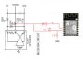
So I googled a bit and found the electric schema of the unit and I had an idea. Can I attach my esp8266 to the pins of the onboard IR receiver of the unit?
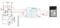
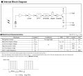
I attached the block diagram and electric data of the receiver and my hypothetical circuit where in black is the actual circuit and in red is my circuit.

I'm asking help because I'm mainly a software developer. Can it work? I don't know if it is needed the diode and I added a transistor to avoid loopback when my unit is transmitting.
The transistor is normally conducting so the esp8266 is always listening for incoming IR codes but if receive a command to be transmitted it close the input line, transmit the code then reopen the input line.

I'll saved the IR codes from remote controller using another tasmota device with IR receiver.

What do you think?
 

Attachments

Irving

Joined Jan 30, 2016
3,843
Your diode is the wrong way round (it's pull-down signalling) and needs to be a Schottky type for this to work, but this is a common way to multi-drop onto a single serial connection.

While transmitting you'll have to monitor the receive side to make sure the UR isn't corrupting what you're sending.

You don't really need the line driver, you can probably direct connect to the IR being mindful of voltage levels. You'll need two resistors on the Rx line as a voltage divider.
 
Last edited:

Thread Starter

valepe69

Joined May 28, 2019
15
Your diode is the wrong way round (it's pull-down signalling) and needs to be a Schottky type for this to work, but this is a common way to multi-drop onto a single serial connection.
Thanks, I supposed that in this direction diode will block the IR pulses, originated from the builtin receiver, to reach the transmitting pin (but is it needed?). Thanks for the schottky suggestion.
While transmitting you'll have to monitor the receive side to make sure the UR isn't corrupting what you're sending.
Well, in this case a corrupted stream will be discarded from the cpu as you press two button on two remote controllers. Am I wrong?
You don't really need the line driver, you can probably direct connect to the IR being mindful of voltage levels. You'll need two resistors on the Rx line as a voltage divider.
About voltage divider, I thinked about it but Esp8266 outputs 3.3V, maybe the onboard cpu doesn't care about it.
 

Irving

Joined Jan 30, 2016
3,843
The IR unit is an open collector output so it only needs a pull-down to signal, the default state is high.

You don't need the transistor in the Rx line to the ESP, it's normal to monitor your own transmission on a 1-wire circuit. You need to do so if you're trying to maintain state of the device. If the IR receives a transmission you get it too and can record the state of the device. If you send a command you need to know it wasn't corrupted by an incoming IR transmission so you can still accurately reflect the state. You know if your transmission is corrupted that the device will ignore both the incoming IR and yours, so no change if state needed. You then back off a random time period and try again (or wait for another Wi-Fi user request if this was originally human generated rather than system generated).
 

Thread Starter

valepe69

Joined May 28, 2019
15
The IR unit is an open collector output so it only needs a pull-down to signal, the default state is high.

You don't need the transistor in the Rx line to the ESP, it's normal to monitor your own transmission on a 1-wire circuit. You need to do so if you're trying to maintain state of the device. If the IR receives a transmission you get it too and can record the state of the device. If you send a command you need to know it wasn't corrupted by an incoming IR transmission so you can still accurately reflect the state. You know if your transmission is corrupted that the device will ignore both the incoming IR and yours, so no change if state needed. You then back off a random time period and try again (or wait for another Wi-Fi user request if this was originally human generated rather than system generated).
I updated the circuit. Did I make all changes correctly?
 

Attachments

if you ignore "corruption", you just need an open collector transistor to gorund n the signal line to xmit and a way to monitor the transmission.

Your transmission here would not have the carrier signal, so it's a different "non-IR" code.

You might be able to use a gate (XOR, NAND?) to monitor, your transmission and actual transmission and determine if there is corruption. So, your processor would have a "corruption" input.
Your expecting the same signal on transmit (your transmit pin) and "the gate" output.
 

Irving

Joined Jan 30, 2016
3,843
No diode is still incorrect, but you probably need to put a transistor there because of the pull up to 5v shown here and an additional one inside the outside unit (this is to control a Sharp a/c unit? I've done something similar with my Daikin). I'll draw it for you...
 

Thread Starter

valepe69

Joined May 28, 2019
15
No diode is still incorrect, but you probably need to put a transistor there because of the pull up to 5v shown here and an additional one inside the outside unit (this is to control a Sharp a/c unit? I've done something similar with my Daikin). I'll draw it for you...
Yes, it's a Sharp unit. Thank you very much, I'll wait your example.
Mmhh, why in the outside unit also? The cpu is inside each of the indoor units. Each unit has four cable: Earth, Neutral, Live and Signal but the lattest is for a lot of communication between the indoor cpu's and the outside cpu.
 

Irving

Joined Jan 30, 2016
3,843
if you ignore "corruption", you just need an open collector transistor to gorund n the signal line to xmit and a way to monitor the transmission.

Your transmission here would not have the carrier signal, so it's a different "non-IR" code.

You might be able to use a gate (XOR, NAND?) to monitor, your transmission and actual transmission and determine if there is corruption. So, your processor would have a "corruption" input.
Your expecting the same signal on transmit (your transmit pin) and "the gate" output.
At this point its not clear if the OC output is normal UART signalling or IRDA signalling. It would appear from the datasheet that its is carrier free. Whether Sharp used the IRDA protocols or not needs to be by experiment.

Wire up the receive side with the 2 resistors and see what your read in... you can't use a UART, you have to use bit-banging but there is a library already available which should help., see this example. It seems that library may already support your A/C unit

AH-AxSAY A/C
AH-XP10NRY A/C
AY-ZP40KR A/C
CRMC-820JBEZ remote
CRMC-A907 JBEZ remote

You may need to use different pins because the ones you've chosen are associated with UART0 which is used for programming.

1594392366684.png
 

Attachments

Irving

Joined Jan 30, 2016
3,843
Mmhh, why in the outside unit also? The cpu is inside each of the indoor units. Each unit has four cable: Earth, Neutral, Live and Signal but the lattest is for a lot of communication between the indoor cpu's and the outside cpu.
I was having a senior moment... it goes to to the microcontroller from the display panel
 
The datasheet can be obtained from here: https://pdf1.alldatasheet.com/datasheet-pdf/view/42829/SHARP/GP1U261X.html

It's for 38 kHz carrier. the signal that comes out of the IR reciever is devoid of the carrier signal. Depending on the protocal, but the usual modulation scheme is pulse position modulation. The 'length" of the pulse determines "1" or '0". there generally are "words" associated with commands. e.g. 5bit or 8 bit. It's not UART type of communication.

NEC added a bunch of 1's for the receiver to adjust it's gain before starting the real command.

The transmitter "gates" or turns on a burst of carrier. for a specific time for a "1" or "zero". The duty cycle of the carrier is usually less than 50% to save power.

The signal "sent" to the IR transmit LED is not the same demodulated signal from this detector.

"corruption" may be hard to detect, but you don't want to be transmitting when the remote is transmitting. Usually, you wait a random length of time and check again.

This https://techdocs.altium.com/display/FPGA/NEC+Infrared+Transmission+Protocol does show the NEC protocal, but does not do a good job explaining the carrier.
 

Thread Starter

valepe69

Joined May 28, 2019
15
At this point its not clear if the OC output is normal UART signalling or IRDA signalling. It would appear from the datasheet that its is carrier free. Whether Sharp used the IRDA protocols or not needs to be by experiment.

Wire up the receive side with the 2 resistors and see what your read in... you can't use a UART, you have to use bit-banging but there is a library already available which should help., see this example. It seems that library may already support your A/C unit

AH-AxSAY A/C
AH-XP10NRY A/C
AY-ZP40KR A/C
CRMC-820JBEZ remote
CRMC-A907 JBEZ remote

You may need to use different pins because the ones you've chosen are associated with UART0 which is used for programming.

View attachment 211794
Looking at your circuit D7 is for listening and D8 is for transmissions. Do I understand right?
 
Last edited:

Irving

Joined Jan 30, 2016
3,843
No, I've drawn it as D7 transmit, D8 receive, but you could swap them.

I just realised you've shown the direct Wemos module connections rather than the D1 mini board pins so you used, I think GPIO12 for Rx & GPIO14 for Tx whereas I've used GPIO13 for Tx & GPIO15 for Rx.

If you meant to use GPIO12 & GPIO14 then it should be D5 for Tx and D6 for Rx.

(I think, it's easy to get confused!)
 
Top