Facebook
 Google
 GitHub
 Linkedin
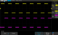
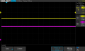
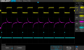
It looks like the timebase pulse width is similar to the output pulse width. Are you sure you are using and measuring the correct timebase signal?The ouput is a squarewave initiated by the falling
edge of the timebase signal but it is not a narrow pulse. See attached.
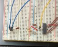
Control Circuit
- Thread starter juan_epstein
- Start date