Control Circuit

crutschow

Joined Mar 14, 2008
38,503
When I use a 2Hz timebase channel 1 is a straight line that jumps up and down while channel 2 is a stationary straight line.
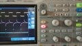
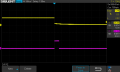
You need to reduce the TIM/DIV to about 500ms/div as MrChips noted, and adjust the trigger to get a stable display.

It would seem you don't understand much about how your oscilloscope works.
I suggest you look up a tutorial on that.
 

Thread Starter

juan_epstein

Joined Sep 1, 2024
28
When you change the input signal from 1 kHz to 2Hz you need to change the TIM/DIV accordingly. You also need to change triggering to MANUAL.
hello

I just got this scope in July and I haven't used it until this week. I am not familiar with all the
controls etc. I don't see a TIM/DIV control or a manual trigger control. I would be grateful if
you could explain what I need to do.
 

Attachments

MrChips

Joined Oct 2, 2009
34,807
hello

I just got this scope in July and I haven't used it until this week. I am not familiar with all the
controls etc. I don't see a TIM/DIV control or a manual trigger control. I would be grateful if
you could explain what I need to do.
On your oscilloscope, HORIZONTAL is TIME/DIV.
NORMAL is MANUAL.
 

Thread Starter

juan_epstein

Joined Sep 1, 2024
28
When you change the input signal from 1 kHz to 2Hz you need to change the TIM/DIV accordingly. You also need to change triggering to MANUAL.

Edit: If you were able to observe the output pulse correctly at 1 kHz input, you don’t have to change the TIM/DIV. Just change the triggering to MANUAL. Trigger on the falling edge of the input.
It has been set to trigger on the falling edge right from the start. I set it to falling edge of channel 1 input . Signal on channel 2 is very faint.
No signal on channel 3 that I can see.
 

Attachments

Last edited:

MrChips

Joined Oct 2, 2009
34,807
Note that your trigger level is set to -100mV. Set this into the +ve range, about 2V. Now that you can observe the 2 Hz signal correctly with Horizontal sweep set to 50ms, change this to a shorter value such as 1ms or 100μs.

There are three parts of the oscilloscope.

Input amplifiers
Horizontal sweep
Trigger

You really need to master all three sections of the oscilloscope.
Avoid the temptation of using Auto Setup otherwise you will fail to learn how to use the oscilloscope.
 

Thread Starter

juan_epstein

Joined Sep 1, 2024
28
Note that your trigger level is set to -100mV. Set this into the +ve range, about 2V. Now that you can observe the 2 Hz signal correctly with Horizontal sweep set to 50ms, change this to a shorter value such as 1ms or 100μs.

There are three parts of the oscilloscope.

Input amplifiers
Horizontal sweep
Trigger

You really need to master all three sections of the oscilloscope.
Avoid the temptation of using Auto Setup otherwise you will fail to learn how to use the oscilloscope.
I don't use the Auto Setup because a lot of the time it doesn't give a good result any way.

I figured out what was wrong. I have an LED on the timebase to indicate that it is functioning. Initially
I had a 220Ω current limiting resistor. When I changed it to a 1KΩ, the signal level rose and the circuit
is now working as it should. The only thing that I don't get, is that the pulse width is approx. 61 μs.
Using a 0.1μF cap and a 1KΩ resistor should result in a 100 μs pulse should it not? 0.2μF results in
a 112 μs pulse width.
 

Attachments

Last edited:

crutschow

Joined Mar 14, 2008
38,503
Using a 0.1μF cap and a 1KΩ resistor should result in a 100 μs pulse should it not?
No. Why do you think that?
100µs is the RC time-constant for the voltage to rise 0.632 (63.2%) of the final voltage, but the pulse width is determined by where on that curve the gate triggers.
A value of 61µs indicates its triggering at a voltage of about 0.46RC or 2.3V.

If you look at the gate input voltage you can measure where it trips.
 

MrChips

Joined Oct 2, 2009
34,807
Two things to note.

I have said it before. Don’t drive LEDs directly from logic signals that are required elsewhere in your circuit. Use a driver to drive the LED separate from the rest of the circuit.

The product of R x C is the time-constant of the RC circuit. The pulse width will be different, but the same order of magnitude.
 

Thread Starter

juan_epstein

Joined Sep 1, 2024
28
Two things to note.

I have said it before. Don’t drive LEDs directly from logic signals that are required elsewhere in your circuit. Use a driver to drive the LED separate from the rest of the circuit.

The product of R x C is the time-constant of the RC circuit. The pulse width will be different, but the same order of magnitude.
I haven't heard about the LED dirver thing before but it certainly makes sense.

Is the purpose of the time constant to create a time delay between the falling edge of the timebase signal and the pulse?
 

MrChips

Joined Oct 2, 2009
34,807
I haven't heard about the LED dirver thing before but it certainly makes sense.

Is the purpose of the time constant to create a time delay between the falling edge of the timebase signal and the pulse?
No. This RC circuit is a differentiator. It takes the mathematical derivative of the input signal.

1729358055618.png
 

MrAl

Joined Jun 17, 2014
13,702
Thank you for the good explanation!
Hi,

You're welcome :)

But doesn't your scope have a DC operating mode (usually called DC coupling) ?
Many scopes have an AC mode, a DC mode, and a GROUND mode. If you can switch to DC coupling mode you can get all the way down to 0.000001 Hz (or even 0.0 Hz)which is a lot lower than 10Hz.

I will note however that one of my first scopes did NOT have a DC mode, it was AC only, and I had to rig up an analog switch and oscillator to act as a chopper so I could view both 0v and the actual signal at the same time and thus giving me a sort of DC coupling. Even though the actual signal was chopped it worked ok to display DC or very low AC waveforms.
That scope was huge and it used a CRT tube. Hated it but it was all I had at the time and I got it for something like $20 USD.
 

Thread Starter

juan_epstein

Joined Sep 1, 2024
28
Hi,

You're welcome :)

But doesn't your scope have a DC operating mode (usually called DC coupling) ?
Many scopes have an AC mode, a DC mode, and a GROUND mode. If you can switch to DC coupling mode you can get all the way down to 0.000001 Hz (or even 0.0 Hz)which is a lot lower than 10Hz.

I will note however that one of my first scopes did NOT have a DC mode, it was AC only, and I had to rig up an analog switch and oscillator to act as a chopper so I could view both 0v and the actual signal at the same time and thus giving me a sort of DC coupling. Even though the actual signal was chopped it worked ok to display DC or very low AC waveforms.
That scope was huge and it used a CRT tube. Hated it but it was all I had at the time and I got it for something like $20 USD.
Hi

Those days are sure gone. My scope does have a dc mode but my senior brain wasn't firing on all cylinders at the time.

Cheers
 

MrAl

Joined Jun 17, 2014
13,702
I think that was due to the difficulty in designing stable DC amplifiers with tubes.
Hi,

I'm not sure when that scope was built for some reason that did not dawn on me at the time. It was gigantic and also had a VTVM built in with it in the same case, which made it larger. It was probably around 18 inches wide 12 inches tall and 16 inches deep, all steel cabinet, and heavy. I kept it on a rolling cart with the replacement transformers on the bottom of the cart.

These days I read NASA might be bringing vacuum tubes back, in a way that is. Micro miniature 'tubes' that are actually just semiconductors with small spaces inside that are evacuated, with the 'anode' and 'cathode' placed very close together (nanoscale) which means they operate on the principle of field emission instead of thermionic emission.
Read about that quite a while back but didn't hear much about it anymore so not sure if they are still working with this idea or not. Benefit is less sensitivity to ambient radiation for space applications.
 
Top