Control Circuit

Thread Starter

juan_epstein

Joined Sep 1, 2024
28
Hello

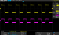
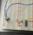
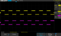
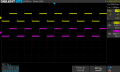
I have a circuit that I want to use as a control for another circuit. I am feeding a 2 Hz square wave of 5 vpp.
The control signal should be a pulse that occurs on the trailing edge of the timebase square wave. I have
attached a spice file for the circuit as well as an image of the actual circuit output on my scope. Thoughts?

Thank you

Juan
 

Attachments

boostbuck

Joined Oct 5, 2017
1,043
a circuit that I want to use as a control for another circuit..... .... attached a spice file for the circuit as well as an image of the actual circuit output ...
There's a lot of circuits here - three? four? It's not so clear which is which tbh. Your spice file has undefined symbols.
I'm taking it you have a square wave that you want to use to generate a narrow pulse.

Perhaps a 555 as an astable would be the answer.

1729030594427.png
 

Thread Starter

juan_epstein

Joined Sep 1, 2024
28
There's a lot of circuits here - three? four? It's not so clear which is which tbh. Your spice file has undefined symbols.
I'm taking it you have a square wave that you want to use to generate a narrow pulse.

Perhaps a 555 as an astable would be the answer.

View attachment 333734
I don't know what you are looking at. There is one circuit and there are no undefined symbols.
Yes, I want to end up with a narrow pulse. The spice file works but the real circuit does not give
me a narrow pulse.
 

Thread Starter

juan_epstein

Joined Sep 1, 2024
28
The capacitor polarity is incorrect.
Plus needs to go towards the plus R1 voltage.

Also put a 1kΩ resistor in series with the bottom CD4093 input to minimize the peak current through the input protection diodes when the power is removed.

I made those changes that you suggested and now there is no output at all.
 

Thread Starter

juan_epstein

Joined Sep 1, 2024
28
Then I suspect a wiring error or an incorrect part.
Double check all the wiring, and the IC pin designations.
I am speaking about the simulation. Here is the simulation. The 1K resistor in series with the lower input is causing the problem.
Also, I thought that this circuit would create a pulse, not a duplicate of the time base.
 

Attachments

Thread Starter

juan_epstein

Joined Sep 1, 2024
28
No, it's not.
My sim below looks fine:

Note I used my own CD4000 lib file.
Do you have one?

View attachment 333738
Hi:

I have such a library but maybe it isn't the best. I see that you changed some component values.
I also had misunderstood the resistor configuration an consequently I wired the sim incorrectly.
It worked for me as well. I will modify my breadboarded circuit as well. By the way, how do you
determine what values to use here?

Thanks
Juan
 

Thread Starter

juan_epstein

Joined Sep 1, 2024
28
No problem. Yes, I guess it would work. I mustn't have seen that the CD4049 was a hex inverter.
Time to get the eyes checked.
I modified my circuit in both the simulator and the breadboard. I do not understand the
results on the breadboard. I thought that I would see a narrow pulse on channel 2 as
per the simulation. Please see attachments.
 

Attachments

Thread Starter

juan_epstein

Joined Sep 1, 2024
28
Yes you should.
As I said previously, I suspect a wiring error or an incorrect part.
Double check all the wiring, and the IC pin designations.
Do you have power and ground to the IC?
I have checked everything. Here is an image of the circuit. The
timebase signal is applied to the negative terminal of the cap.
The voltage on pin#1 is 3.99, I would have expected 5V. Pin#2
is 3.99. Pin#3 voltage is 5.24.
 

Attachments

Last edited:

crutschow

Joined Mar 14, 2008
38,503
What is generating the timebase signal?
Is it indeed 0V and 5V?

What is the polarity of the capacitor?

All unused inputs (not outputs) should be connected to ground.
 

Thread Starter

juan_epstein

Joined Sep 1, 2024
28
I have checked everything. Here is an image of the circuit. The
timebase signal is applied to the negative terminal of the cap.
The voltage on pin#1 is 3.99, I would have expected 5V. Pin#2
is 3.99. Pin#3 voltage is 5.24.
UPDATE

I modified the circuit and I at least have an output from the breadboarded
circuit. All unused input are at 0V. I am now using a 100nF ceramic disc cap
and a 100K resistor. The ouput is a squarewave initiated by the falling
edge of the timebase signal but it is not a narrow pulse. See attached.
 

Attachments

Last edited:

crutschow

Joined Mar 14, 2008
38,503
The ouput is a squarewave initiated by the falling
edge of the timebase signal but it is not a narrow pulse.
Perhaps you have a bad IC.
Do have another you can try?

It's acting like the capacitor is shorted.

Post a picture of your latest circuit breadboard.
 
Last edited:
Top