Contact Sense using an opamp or similar

Thread Starter

anishkgt

Joined Mar 21, 2017
549
As the primary current is quite low there will not be very much voltage drop across the lamp (Or resistor if you use one instead of a lamp.).
The transformer is only switched ON when the weld button is pressed meaning, the transformer is switched ON manually with the press of a button. Are you talking about the leakage current when it is OFF ?

Albert has his own library which needs to be added to his code. The library is on his site without which there would be compile errors.
 

LesJones

Joined Jan 8, 2017
4,509
The idea is that the transformer is partly energised via the lamp to provide some small voltage so that there is some way of knowing that the electrodes are in contact with each other. Without obtaining the small voltage across the electrodes this way then you would need some way to inject a high frequency signal into the wire from the transformer to one electrode in a similar way to the starter circuit on a TIG welder.
I did try loading all the files from the zip file but I could not get it to compile. It was much quicker to just write a program in assembler as I do not understand "C" (At the moment I am trying to understand how termios works to receive a string of bytes on a Raspberry Pi. )

Les.
 

LesJones

Joined Jan 8, 2017
4,509
The lamp is in series with the primary as in the schematic. When the weld current is required the SCRs are triggered shorting out the lamp and applying the full mains voltage to the primary.

Les.
 

Thread Starter

anishkgt

Joined Mar 21, 2017
549
I think there would be a simpler way.

I just checked the OFF-State voltage at the thyristor and it read 1.05VAC and when the secondary was shorted it was 0.5VAC.

I could add a comparator in parallel to monitor the voltage variation and use the out of the op-amp to trigger the thyristor.
CS.PNG
 

LesJones

Joined Jan 8, 2017
4,509
In your schematic above (Post #26) you have no isolation between the mains and the control logic. Also you are sensing the voltage drop across a length of wire with an undefined resistance. And finaly you have transformer fully powerd with 240 volts on the primary so as soon as the electrodes touch the metal you have the full welding current available. As an alternative to the small transformer in my schematic you could use a photo detector close to the lamp to trigger the weld pulse circuit as the lamp will light up or become brighter (Depending on it's power rating.)

Les.
 

Thread Starter

anishkgt

Joined Mar 21, 2017
549
I am running out of space on the pcb and adding a bulb wouldn’t be a very good idea either in terms of design nor adding a transformer.

So I was thinking of a shunt resistor in series and a voltage reference from a pcb transformer already used in the design but am not sure which Opamp to use.

Any suggestions on the opamp anyone ?
 

Thread Starter

anishkgt

Joined Mar 21, 2017
549
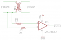
I came across this circuit and it seems to suit my application. What diodes should be used here ? There application here seems to be clamping. I was hoping to use it as a comparator. would that be ok ? what would be the best comparator for this, LM741 ? and would it be ok to use 1N4001 diodes ? and values for R1 and R.
 

Thread Starter

anishkgt

Joined Mar 21, 2017
549
I feel this would be a better design, once the transformer is switched on for spot welding the opamp would be protected as the Opto-coupler would not be enabled because the LED within the opto is controlled by the MCU.
 

AnalogKid

Joined Aug 1, 2013
12,199
My circuit detects the zero cross on the AC sine wave and triggers two Thyristors in a back-to-back configuration which switches on a MOT(Microwave Oven Transformer) at the peak of the sine, which is the typical way to switch on inductive loads to avoid inrush currents.
I don't think that is correct. When applying power to an *uncharged* inductance, nothing has less inrush current than zero volts. The impedance can be simple, complex, positive, negative - whatever; zero volts is zero volts.

After that, the risetime of an AC power line source always will be slower than of a sine wave peak (or any non-zero instantaneous voltage value) applied through the near-infinite risetime of a switch, so zero-voltage turn on is the minimum inrush current case.

Turning *off* the transformer at zero current has merit because once the inductance is inducting, zero current and zero voltage occur at different times. But at turn-on, they are the same.

ak
 

Thread Starter

anishkgt

Joined Mar 21, 2017
549
“A zero-crossover solid-state relay may be the worst possible method of switching on a transformer or a highly inductive load. Evidence has come to light that zero-crossover turn-on of such loads can cause a surge current of perhaps 10 to 40 times the steady state current, whereas turn-on at peak voltage results in little or no surge.”

From TE app note http://www.te.com/commerce/Document...v&DocNm=13C3206_AppNote&DocType=CS&DocLang=EN
 
Top